Rear view mirror

a technology for rear view mirrors and mirrors, applied in mirrors, instruments, vehicle components, etc., can solve the problems of compromising the usefulness of such mirrors, unable to quickly perceive the distance between a first vehicle and a user, and unable to quickly allow the user to move, so as to achieve quick perception of a vehicle, simple and inexpensive

Inactive Publication Date: 2006-11-16
ZMARLICKI HIERONIM
View PDF12 Cites 3 Cited by
  • Summary
  • Abstract
  • Description
  • Claims
  • Application Information

AI Technical Summary

Benefits of technology

[0005] It is an object of the invention is to provide a simple and inexpensive mirro

Problems solved by technology

A major disadvantage of such mirrors is that the user cannot perceive the distance between a first vehicle on which the mirrors mounted and a second vehicle that is approaching the first vehicle from the rear.
Smaller mirrors of this type do not allow the user to quickly perceive a ve

Method used


Image

  • Rear view mirror
  • Rear view mirror
  • Rear view mirror

Examples


Embodiment Construction

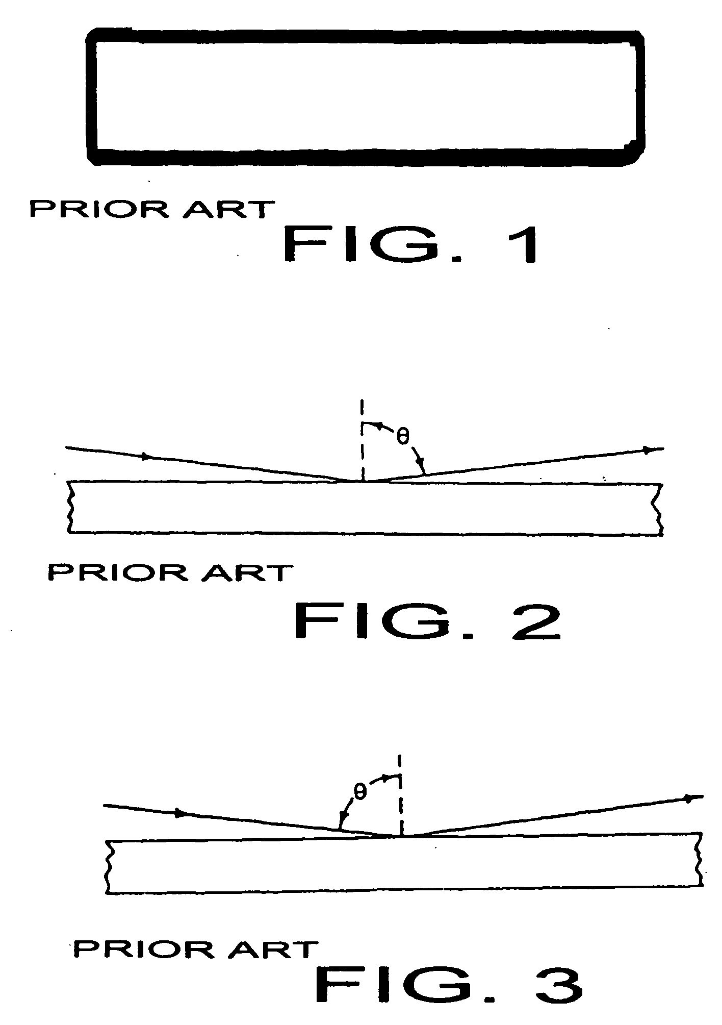
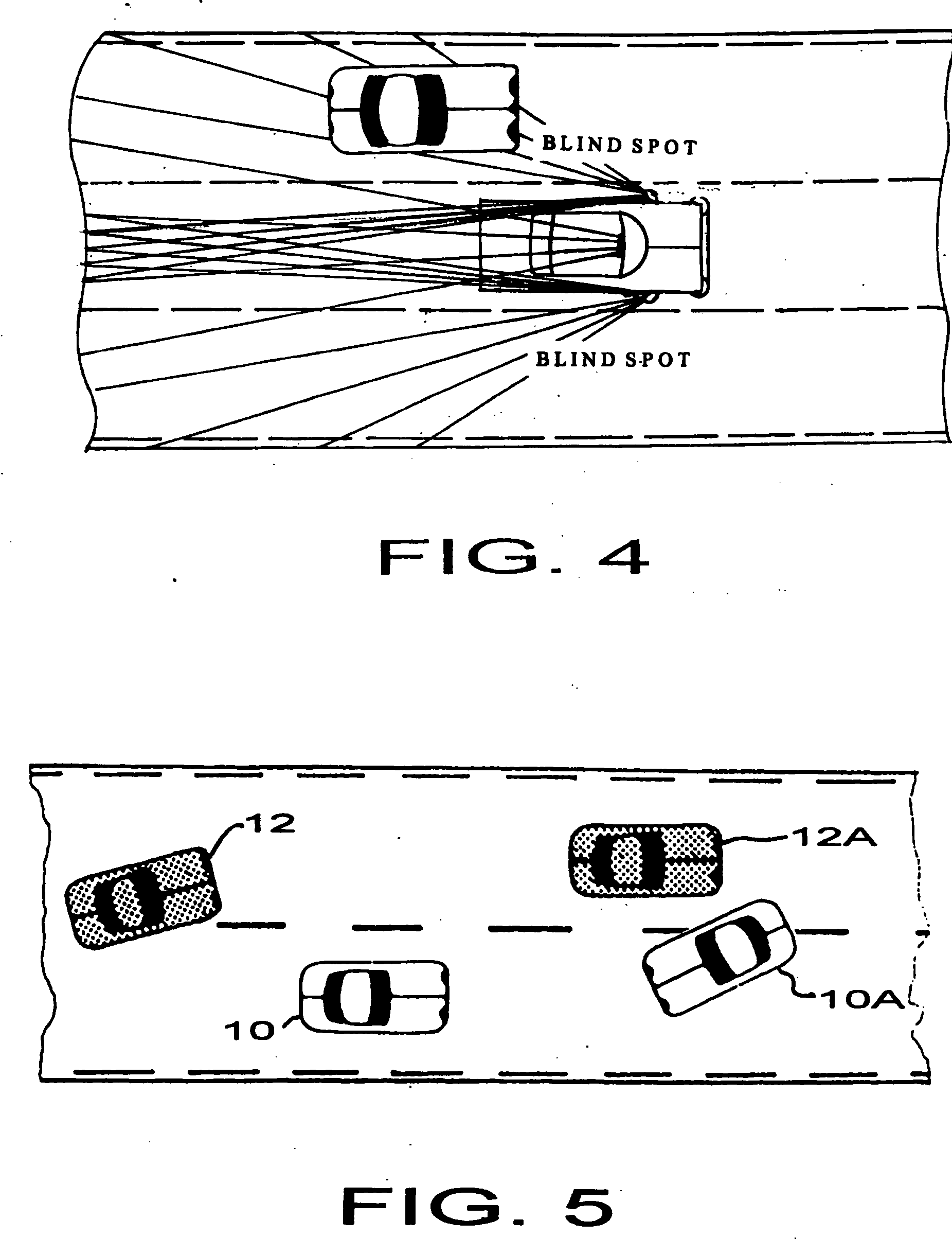
[0017] Referring now to FIGS. 1-5 there are shown a prior art rear view mirror in which the angle of incidence of a light ray is equal to the angle of reflection reset of that light ray. As shown in FIG. 4 the driver of a vehicle moving from left to right, as illustrated, can see a tapered zone behind the vehicle. The driver of the vehicle can not see another vehicle located in the blind zones or spots indicated by cross-hatching.

[0018] As shown in FIG. 5, the driver of a vehicle 10 cannot see the vehicle 12 located in the blind spot of that driver. Subsequent positions of vehicles 10 and 12 are represented in this diagram by the representations identified as 10A and 12A. The driver of the vehicle 10 may, in reliance on his perceptions of situation utilizing the prior art rear view mirror, attempt to move to the left lane and may impact the other vehicle 12A.

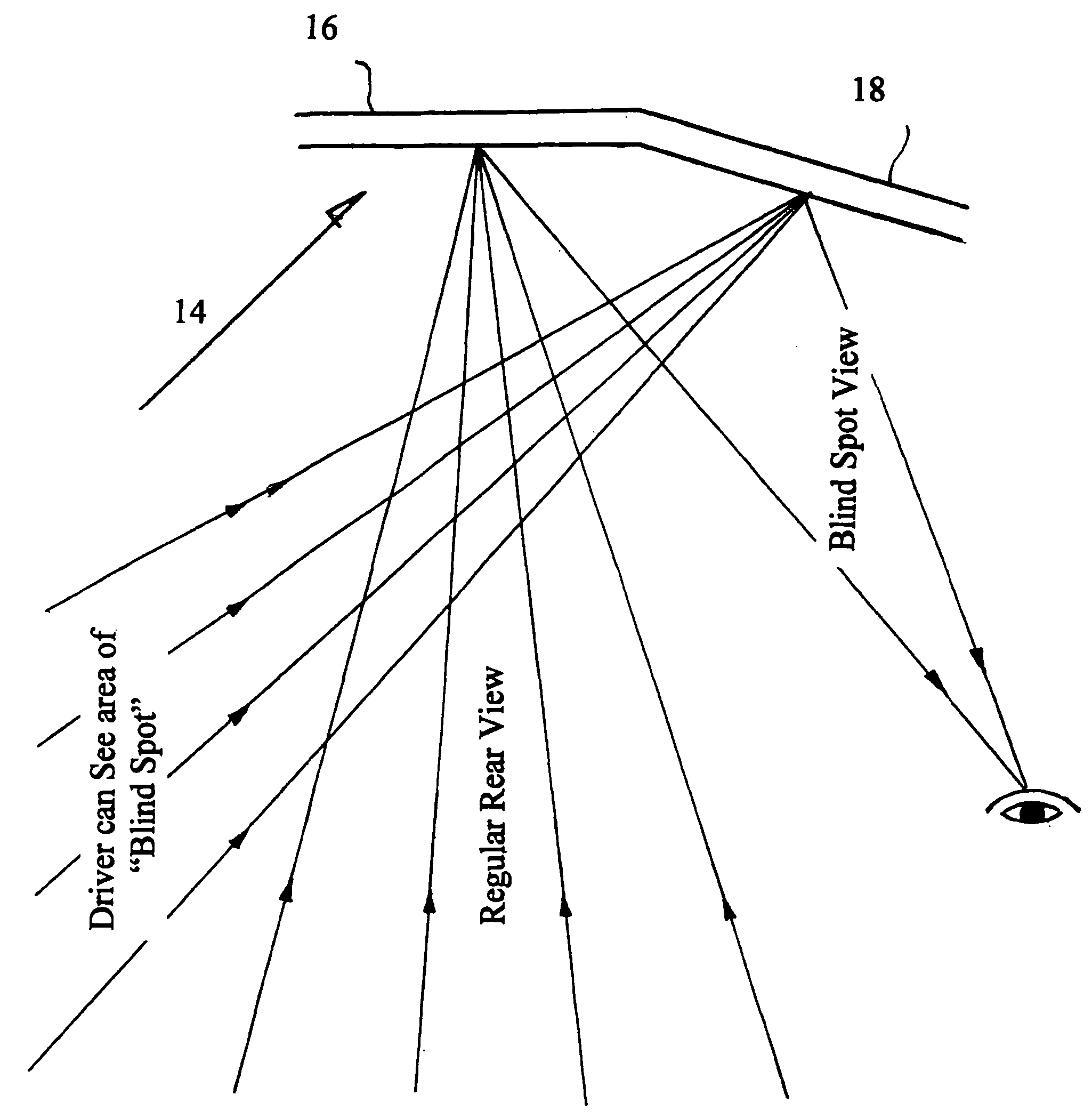
[0019]FIG. 6 illustrates diagrammatically one form of the unitary apparatus 14 in accordance with the present invention. Thi...


PUM


Abstract

A rear view mirror has a single mirror surface. The single mirror surface heads first and second planar reflective portions having an included angle therebetween that is less than 180°. In some cases the mirror is elongated in a direction that is normally horizontal when the mirror is mounted for use and the first and second portions many intersect to define a line that is vertical when the mirror is mounted for use. For some applications an included angle of approximately 160° is preferred. In some cases the first portion is mounted during normal use with the plane thereof substantially normal to the major axis of the vehicle on which the mirror is mounted. For some embodiments, the second portion is to the right of the first portion during normal use. The first portion may be elongated and many more specifically be elongated in a direction that is horizontal during normal use. Similarly, the second portion may be elongated and this elongation may be in a direction that is horizontal during normal use.

Description

FIELD OF THE INVENTION [0001] The invention relates to rear view mirrors suitable for use on cars, trucks, buses, etc. While the primary application of the invention is for a mirror that is mounted on the windshield, typically near the top central portion of the windshield, those skilled in the art will recognize that some embodiments of the rear view mirror in accordance with the present invention may also be used for bicycles, motorcycles, and a wide range of other applications. BACKGROUND OF THE INVENTION [0002] The prior art includes a wide variety of vehicle rear view mirrors. The most common form of rear view mirror that is mounted to the windshield near the top and central portion thereof is a planar reflective surface characterized by the traditional laws of physics wherein the angle of incidence of light is equal to the angle of reflection of light. [0003] Concave and convex mirrors have been widely used for side mirror applications. A major disadvantage of such mirrors is ...

Claims


Application Information

Patent Timeline
IPC IPC(8): G02B5/08
CPCB60R1/08
Inventor ZMARLICKI, HIERONIM
Owner ZMARLICKI HIERONIM
Why Eureka
Try Eureka