Slide pad notebook pointing device with sealed spring system

a technology of sealing springs and notebooks, applied in the direction of instruments, computing, electric digital data processing, etc., can solve the problem of not being able to use the same device in portable and hand-held computers

Inactive Publication Date: 2006-12-28
AVAGO TECH ECBU IP (SINGAPORE) PTE LTD
View PDF8 Cites 17 Cited by
  • Summary
  • Abstract
  • Description
  • Claims
  • Application Information

AI Technical Summary

Problems solved by technology

While the mouse has provided a satisfactory solution to the pointing device problem in the desktop PC market, a similarly successful device is not available for portable and hand-held computers.
Further, the pointing device must operate in a limited workspace and fit within the form factor of the computer or hand held device.

Method used


Image

  • Slide pad notebook pointing device with sealed spring system
  • Slide pad notebook pointing device with sealed spring system
  • Slide pad notebook pointing device with sealed spring system

Examples


Embodiment Construction

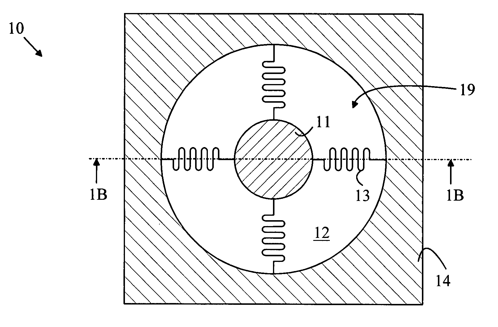
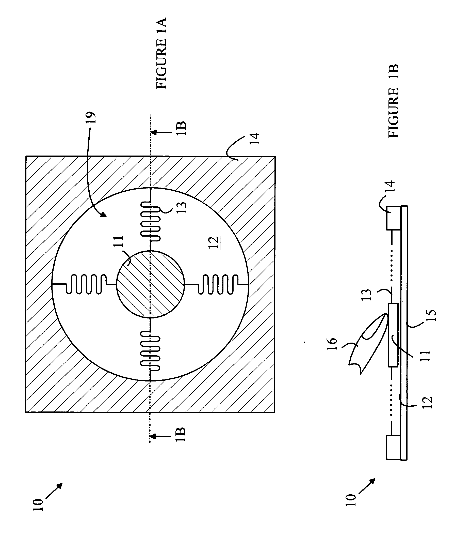
[0020] The manner in which the present invention provides its advantages can be more easily understood with reference to FIGS. 1A and 1B, which illustrate a pointing device 10 according to one embodiment of the invention taught in the above-described patent application. FIG. 1A is a top view of pointing device 10, and FIG. 1B is a cross-sectional view of pointing device 10 through line 1B-1B shown in FIG. 1A. Pointing device 10 includes a puck 11 that moves over a surface 12 of a substrate 15 within a puck field of motion 19 in response to a lateral force applied to puck 11. The force is typically applied to puck 11 by a user's finger. Puck 11 optionally includes a pressure sensing mechanism that measures the vertical pressure applied to puck 11. In addition, pointing device 10 includes a sensing mechanism for determining the position of puck 11 on surface 12.

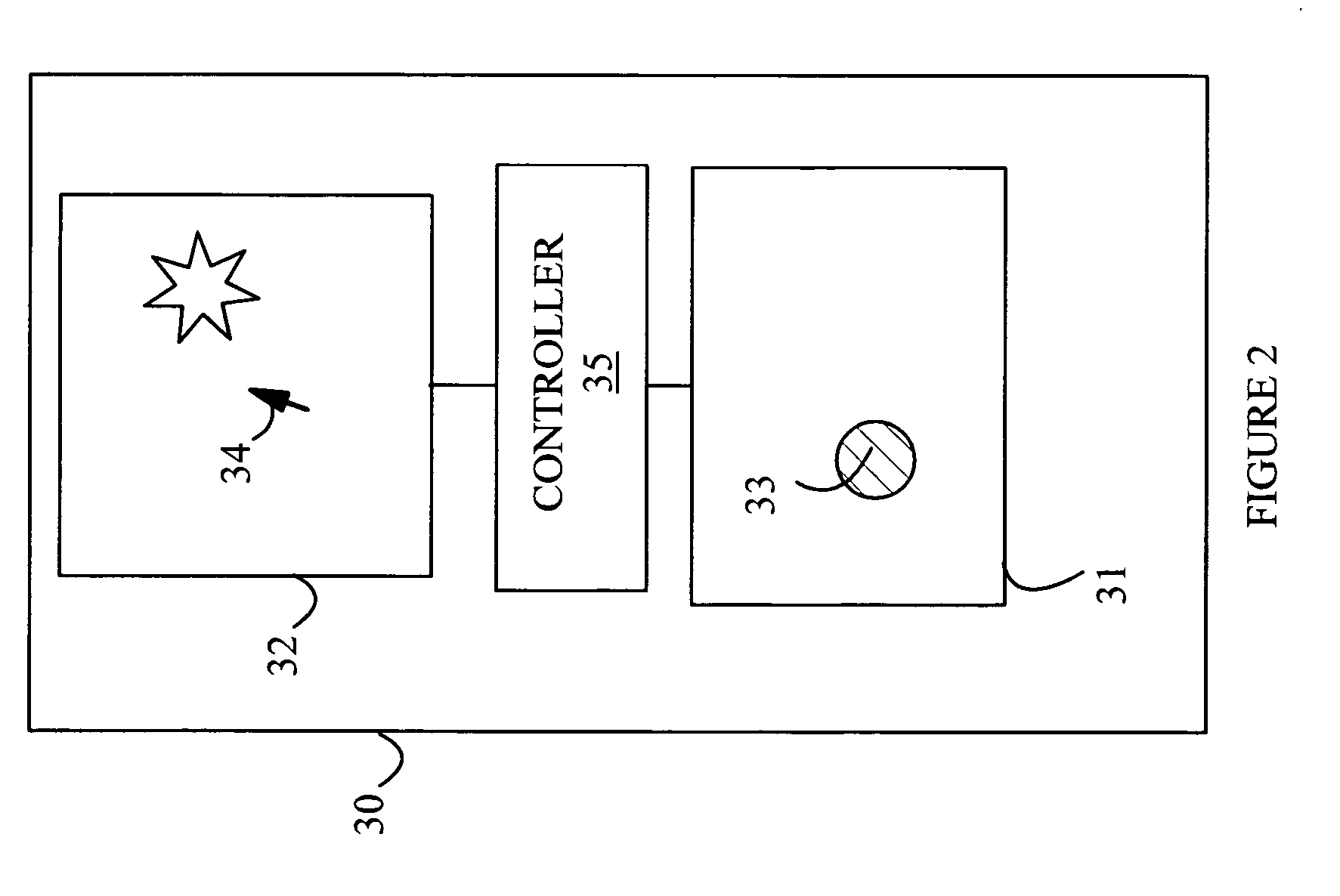
[0021] A pointing device is typically included in a data processing system to control the cursor on the screen of a display ...


PUM


Abstract

A pointing device having top and bottom pucks that move on a stage is disclosed. The top puck moves over the top surface of the stage in response to a lateral force applied thereto. The top and bottom pucks are magnetically coupled such that the two pucks maintain a predetermined relative position with respect to one another. A position sensor generates a signal indicative of the location of the bottom puck. The pointing device can also include a pressure signal generator that generates a user present signal if the top puck is subjected to a force greater than a first force level. The determined pressure can also be used to simulate a button being pushed. Exemplary pressure signal generators utilize strain gauges, variable capacitors in the top puck, and circuits for detecting the vertical distance between the top and bottom pucks when the top puck includes a deformable member.

Description

BACKGROUND OF THE INVENTION [0001] To simplify the following discussion, the present invention will be explained in terms of a pointing device for use on a computer; however, the present invention may be utilized with a wide range of data processing systems including hand held computers, cell phones, video games, and the like. Modem computer operating systems and graphics programs require a pointing device for controlling the position of a cursor on the computer display. For desktop PCs, the most successful pointing device is the “mouse”. A mouse is a hand held object that is moved over a flat surface near the keyboard to control the motion of a cursor on the computer display. The direction and distance over which the mouse is moved determines the direction and distance the cursor moves on the display. A conventional mouse provides a rigid object that a user can move with great precision. For a desktop computer, the mouse provides a satisfactory solution to the pointing problem. On ...

Claims


Application Information

Patent Timeline
Patent Type & Authority Applications(United States)
IPC IPC(8): G09G5/08
CPCG06F3/03548
Inventor MATTA, FARIDHARLEY, JONAHSCHROEDER, DALEWARD, CALVIN B.
Owner AVAGO TECH ECBU IP (SINGAPORE) PTE LTD
Why Eureka
Try Eureka