Apparatus and method for switching channels in a digital broadcasting system

a digital broadcasting system and channel switching technology, applied in the field of apparatus and a channel switching method in the digital broadcast system, can solve the problems of inconvenience in that users also have to memorize channel numbers, disadvantageous consumption of a long-term period, and user memorization of channel numbers

a digital broadcasting system and channel switching technology, applied in the field of apparatus and a channel switching method in the digital broadcast system, can solve the problems of inconvenience in that users also have to memorize channel numbers, disadvantageous consumption of a long-term period, and user memorization of channel numbers

US20070016923A1Inactive Publication Date: 2007-01-18SAMSUNG ELECTRONICS CO LTD

Image

  • Apparatus and method for switching channels in a digital broadcasting system
  • Apparatus and method for switching channels in a digital broadcasting system
  • Apparatus and method for switching channels in a digital broadcasting system

Examples


Embodiment Construction

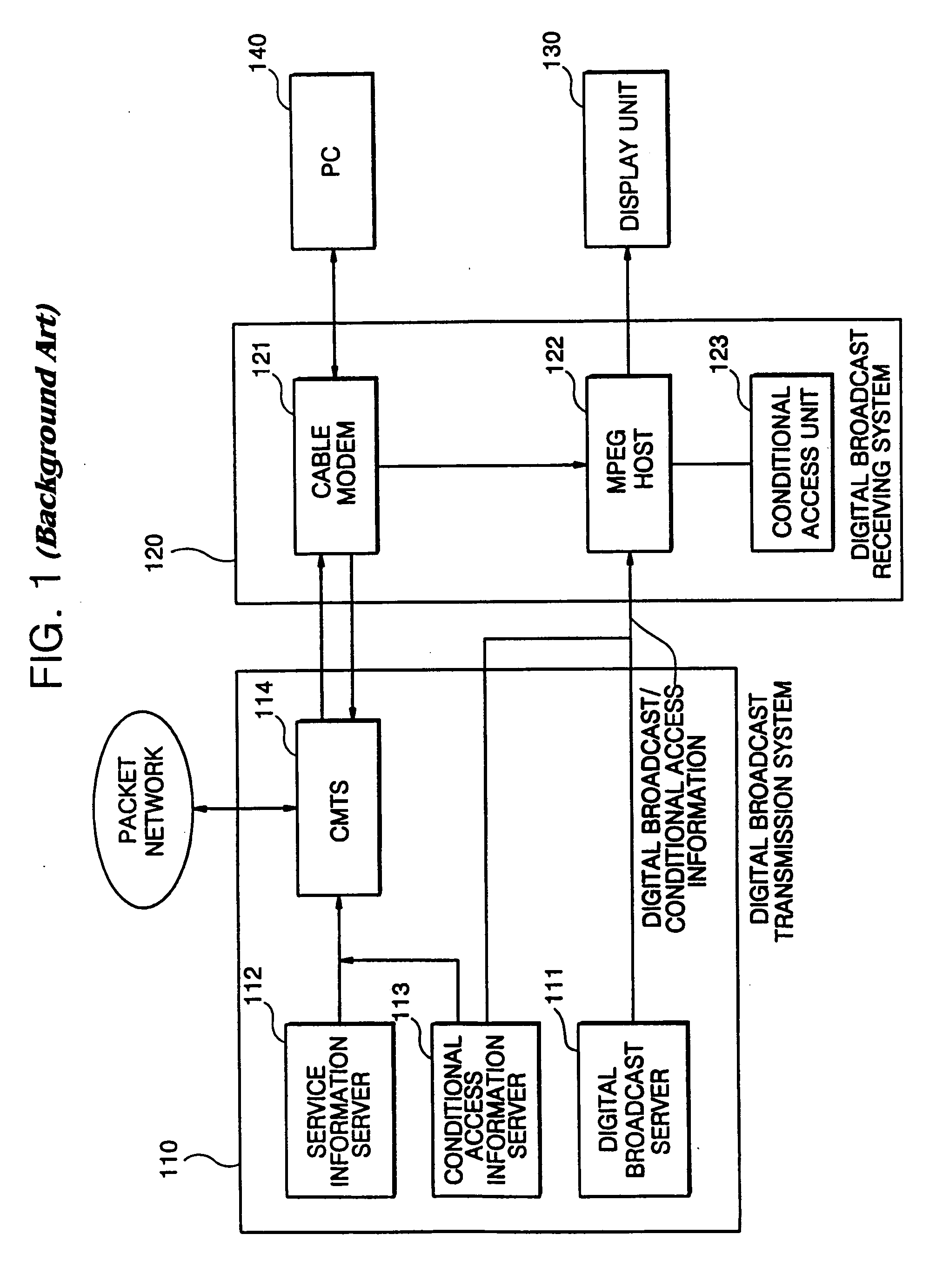
[0030]FIG. 1 is a block diagram illustrating an open cable digital broadcasting system. The open cable digital broadcasting system includes a digital broadcast transmitting system 110 and a digital broadcast receiving system 120 such as a set top box.

[0031] The digital broadcast transmission system 110 may include a digital broadcasting server, or an audio / video server, 111, a service information server 112, a conditional access information server 113 and a Cable Modem Termination System (CMTS) 114.

[0032] The audio / video server 111 is a device for compressing multimedia signals to be transmitted. The service information server 112 is adapted to transmit service information of a broadcast channel, and the conditional access information server 113 allows only specific users to access specific or all contents. The CMTS 114 is a cable head end, converting cable modem data into Internet data packets.

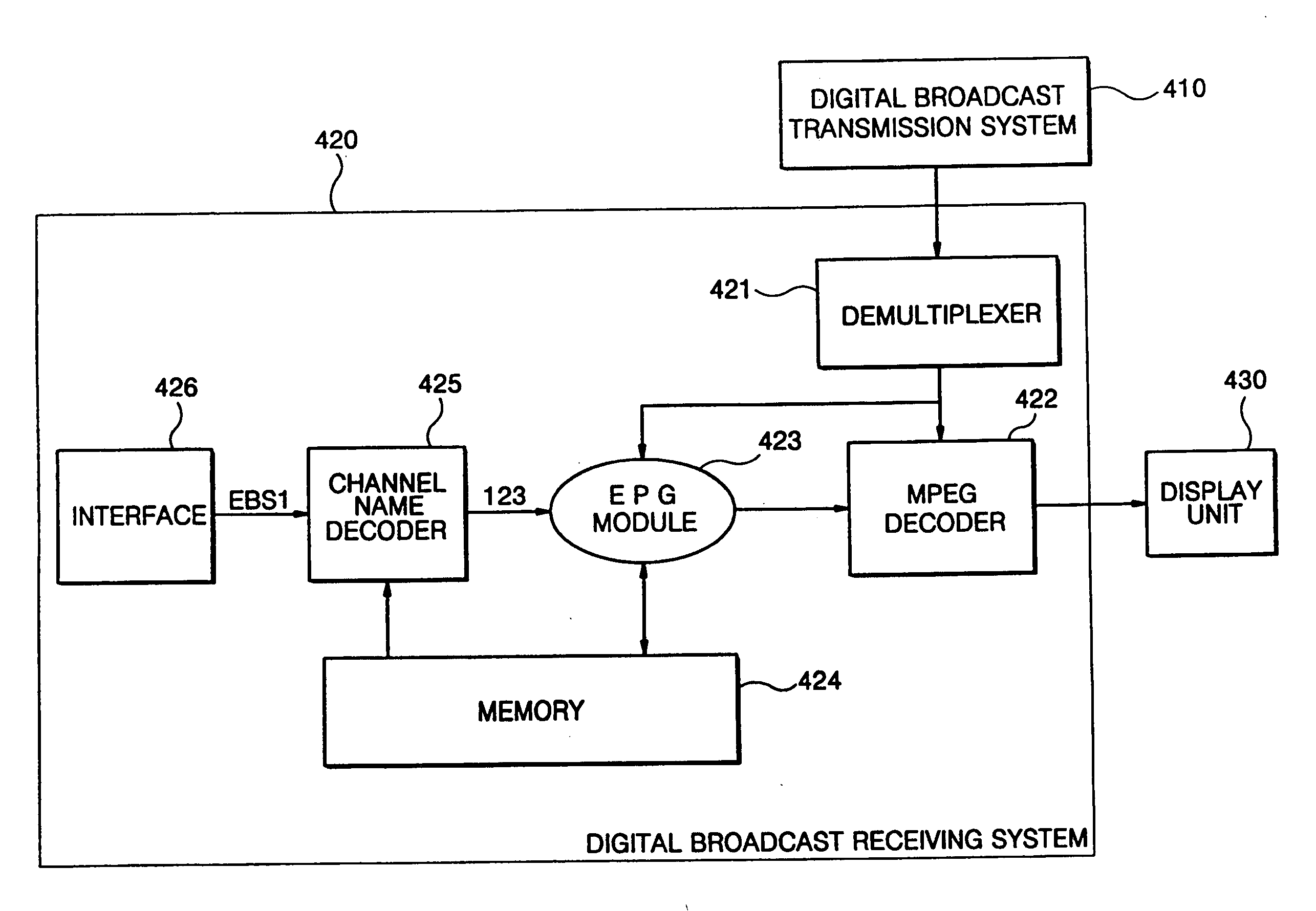
[0033] The digital broadcast receiving system 120 is a device to interpret and display...


PUM


Abstract

An apparatus and a method for switching channels in a digital broadcasting system. The apparatus and method of the invention can convert an abridged channel name comprised of alphabetic letters, or a combination of alphabetic letters and Arabic numbers, inputted by a user, into a corresponding channel number and switches into a digital broadcasting channel at a tuner according to the channel number so that a user can easily switch broadcast channels.

Description

CLAIM OF PRIORITY [0001] This application makes reference to, incorporates the same herein, and claims all benefits accruing under 35 U.S.C. ยง 119 from an application for APPARATUS AND METHOD FOR CHANGING THE CHANNEL IN DIGITAL BROADCASTING SYSTEM earlier filled in the Korean Intellectual Property Office on 12 July, 2005 and there duly assigned Serial No. 10-2005-0062848. BACKGROUND OF THE INVENTION [0002] 1. Field of the Invention [0003] The present invention relates to an apparatus and a method for switching channels in a digital broadcast system. [0004] 2. Description of the Related Art [0005] A digital broadcasting system refers to a television broadcasting system that provides broadcasting by compressing multimedia signals into a digital format by which information signals are written in codes. A conventional analogue television broadcasting system has been able to transmit one image on one channel, but use another channel to broadcast voice. In addition to this, the digital br...

Claims


Application Information

Patent Timeline
18 Jan 2007
Publication
US20070016923A1
IPC
H04N5/50; G06F13/00; H04N7/16; H04N7/173; H04N5/445
CPC
H04N5/44543; H04N5/50; H04N21/482; H04N21/4383; H04N21/422; H04N21/47; H04N7/08
Inventors
KWON, HUNG-ROK