

Fountain
a fountain and fountain technology, applied in the field of fountains, can solve the problems of troublesome candles and inconvenient use of candles, and achieve the effect of safe and convenient us
- Summary
- Abstract
- Description
- Claims
- Application Information
AI Technical Summary
Benefits of technology
Problems solved by technology
Method used
Image

Examples
Embodiment Construction
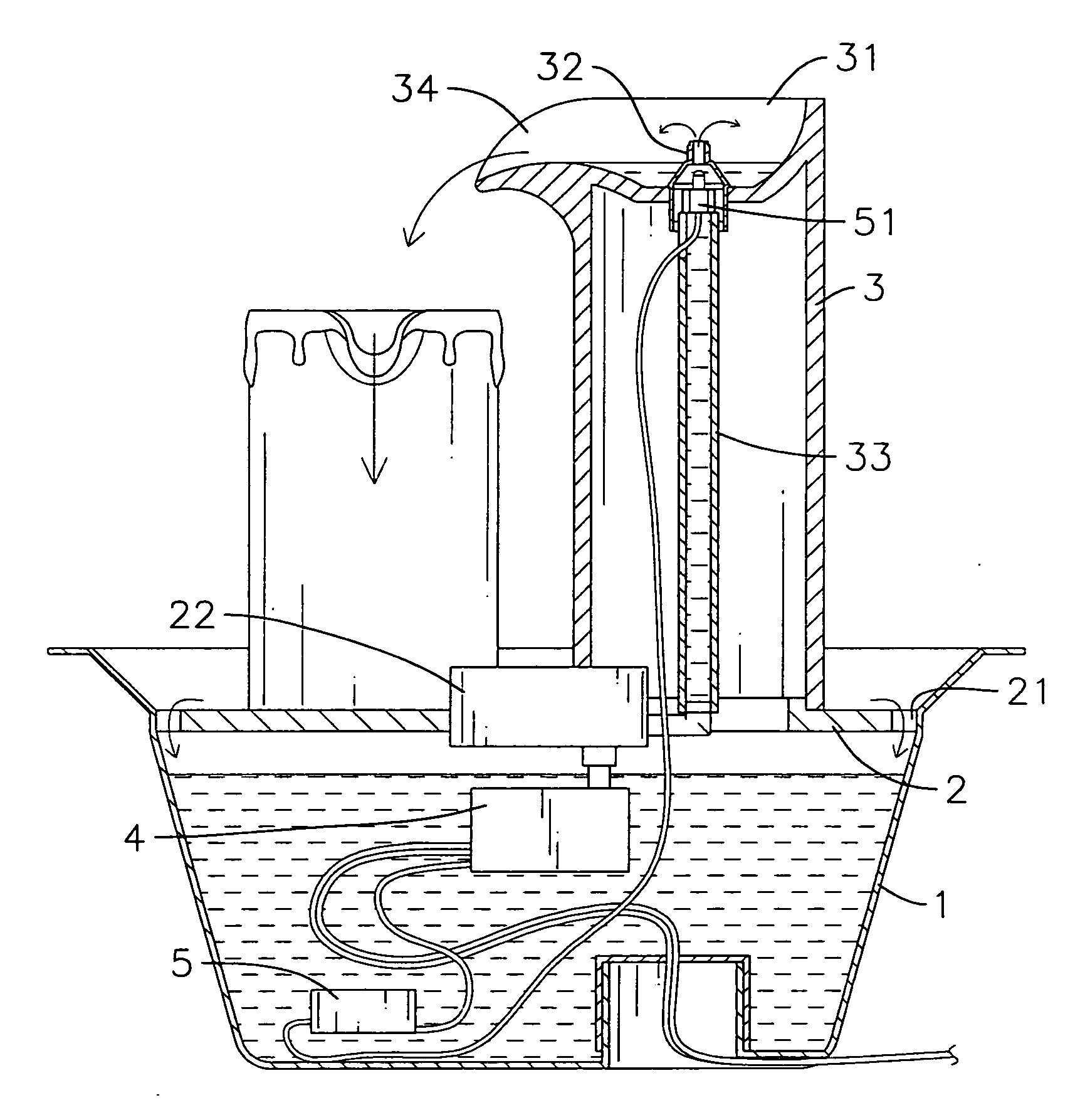
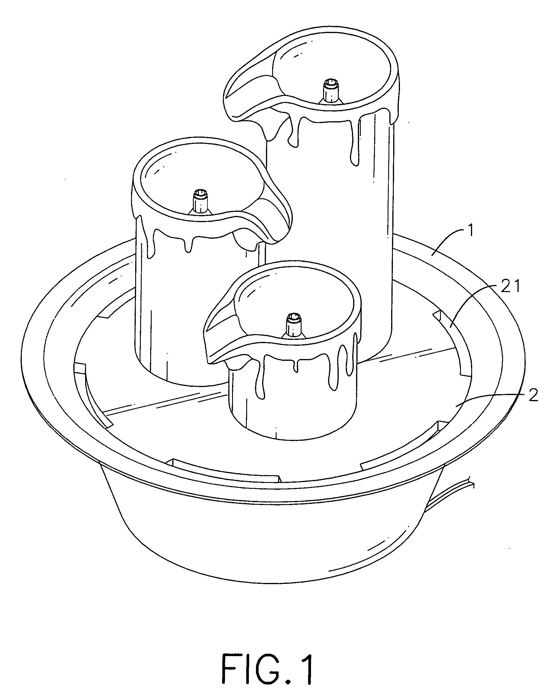
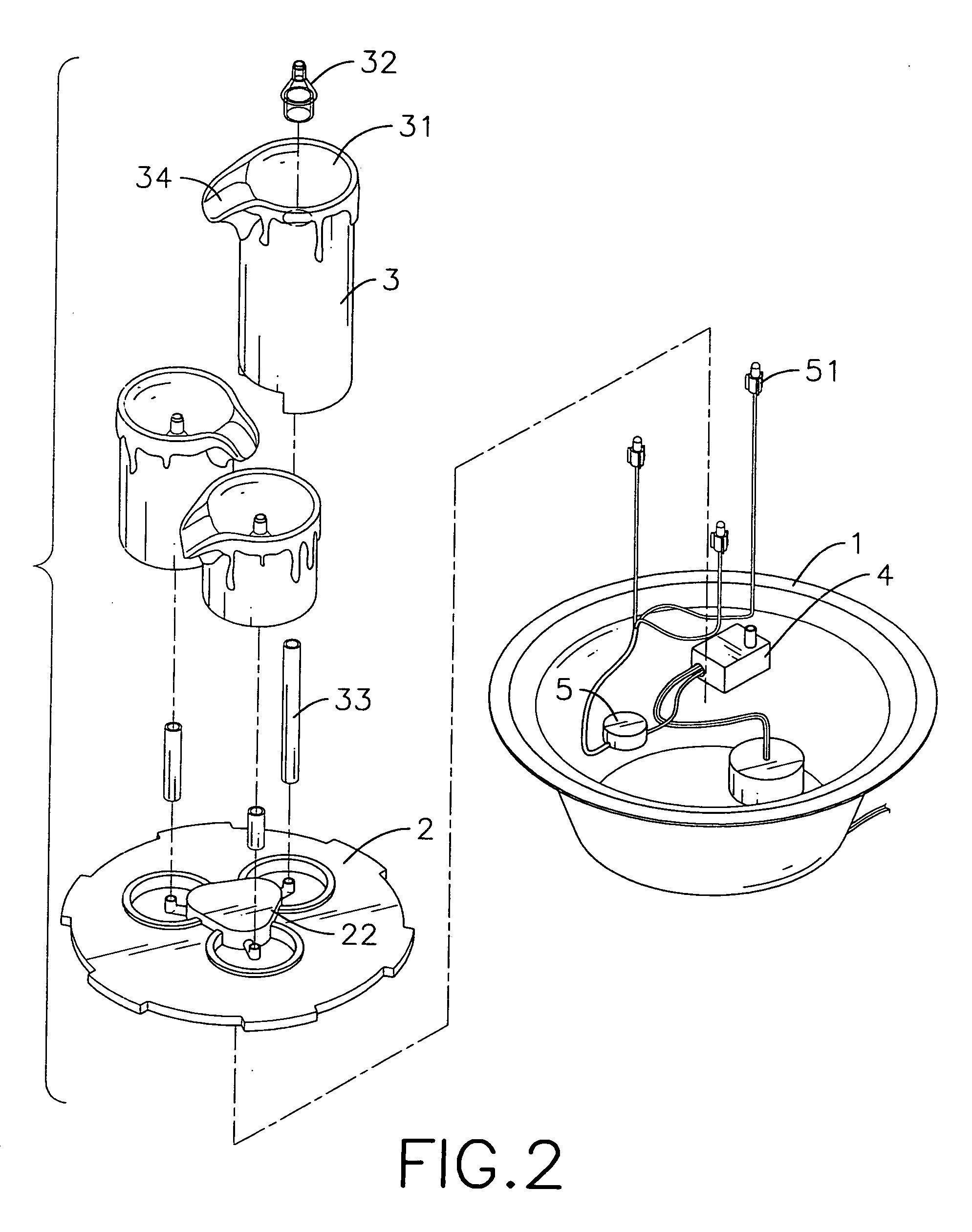
[0017] With reference to FIGS. 1, 2 and 3, a fountain in accordance with the present invention comprises a base (1), an optional cover (2), at least one stand (3), a pump (4) and a lighting assembly (5).
[0018] The base (1) is hollow and has a top opening and a liquid recess. The liquid recess is formed inside the base (1) and holds a liquid.
[0019] The cover (2) is mounted on the top opening of the base (1) and has a side edge, a top surface, multiple cutouts (21) and a tube connector (22). The cutouts (21) are formed in the side edge of the cover (2). The tube connector (22) is mounted on the cover (2) and has an inlet and at least one outlet. The outlet communicates with the inlet.
[0020] Multiple stands (3), for example three stands (3), having different heights may be used. Each stand (3) is mounted in the top opening of the base (1) above the liquid recess, may be mounted on the top surface of the cover (2), may be shaped like a candle and has a top, a top liquid recess (31), ...
PUM
 Abstract
Description
Claims
Application Information