

Fluid dampening chain tensioning device
- Summary
- Abstract
- Description
- Claims
- Application Information
AI Technical Summary
Benefits of technology
Problems solved by technology
Method used
Image

Examples
Embodiment Construction
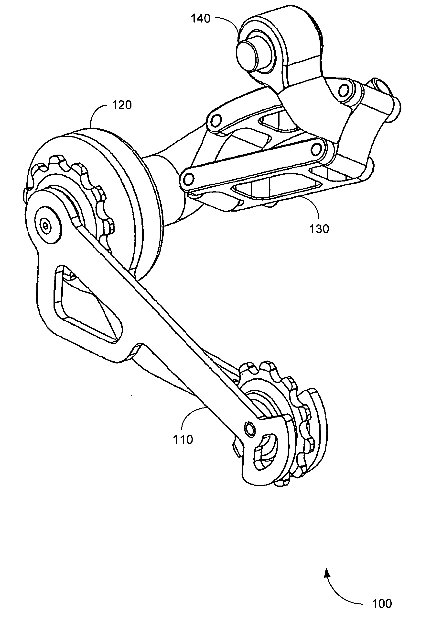
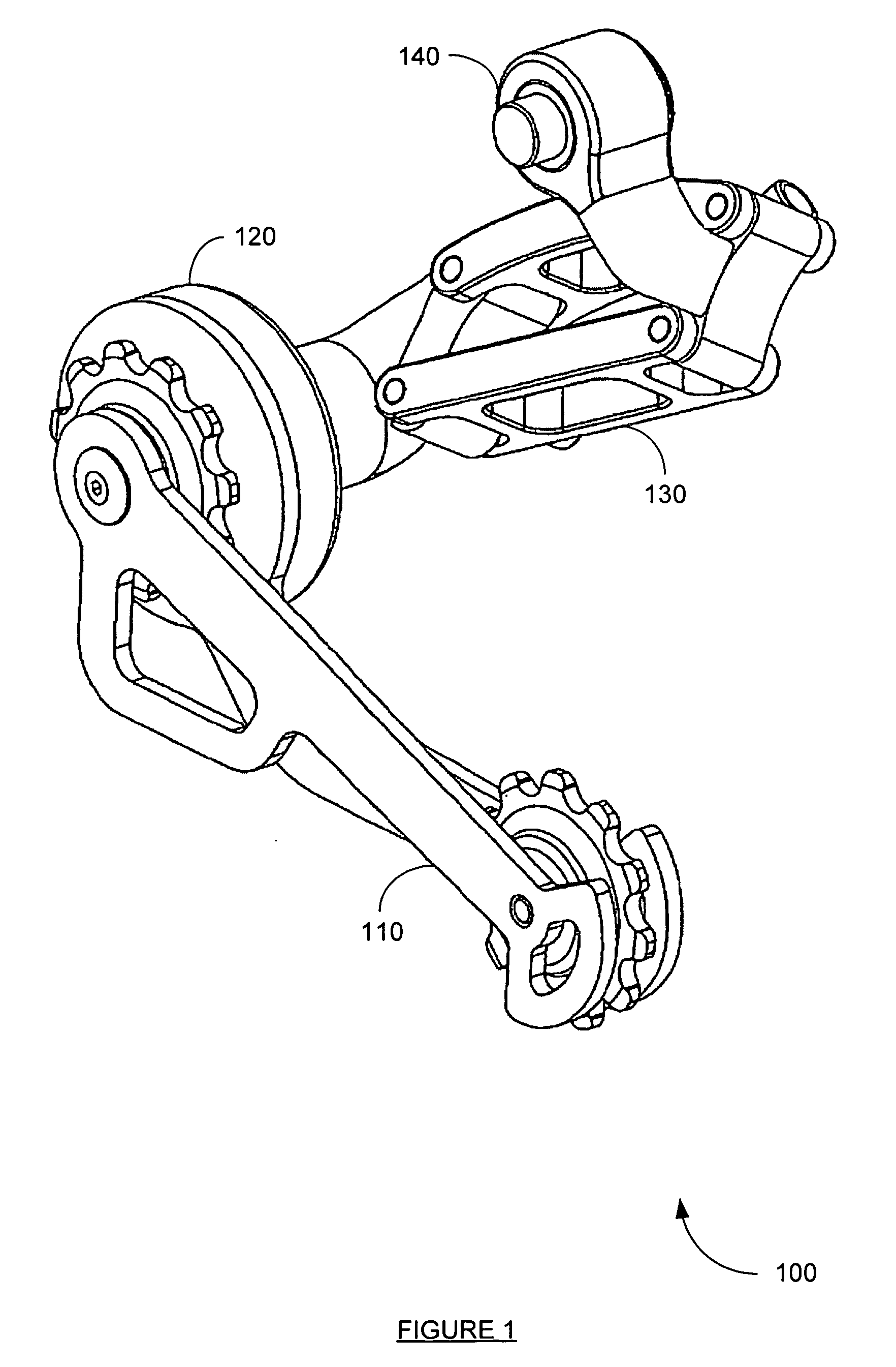
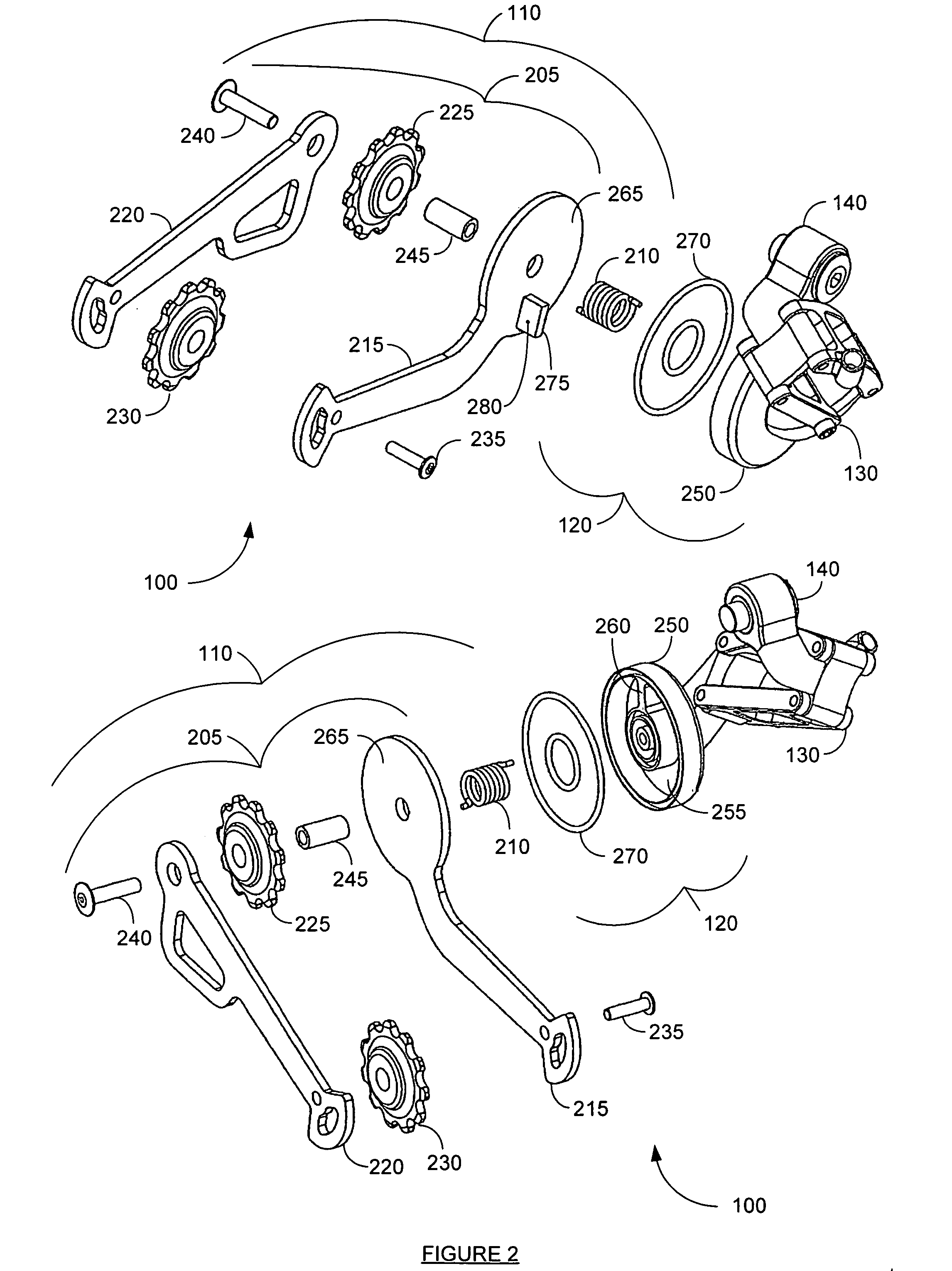
[0024] One embodiment of the invention provides a chain tensioning system having a chain tensioning device and a fluid dampening device. In such an embodiment, the chain tensioning device maintains tension on a chain and the fluid dampening device permits slow movement of the chain tensioning device while dampening sudden movement.
[0025] The chain tensioning device may consist of a link arm assembly that has a pulley which engages the chain. A spring may be used to apply force to the link arm assembly, thereby rotating the link arm assembly, reducing slack in the chain, and maintaining chain tension.
[0026] In some embodiments, the fluid dampening device may consist of two enclosed chambers, each containing a fluid. A fluid path may exist between the two chambers allowing the fluid to move from one chamber to the other. The fluid dampening device may have a rotating component that is operably coupled to the chain tensioning device. As the chain tensioning device moves, the rotating...
PUM
 Abstract
Description
Claims
Application Information