Image forming apparatus

a technology of forming apparatus and forming plate, which is applied in the direction of electric controllers, instruments, ignition automatic control, etc., can solve the problems of paper jamming, sheet cannot be sufficiently loosened, heavy, and large, and achieves high cos

Inactive Publication Date: 2008-02-14
CANON KK
View PDF12 Cites 10 Cited by
  • Summary
  • Abstract
  • Description
  • Claims
  • Application Information

AI Technical Summary

Benefits of technology

[0022]The invention is made in consideration of such a present situation and it is, therefore, an object of the invention to provide an image forming apparatus which can loosen sheets at an optimum wind pressure by using a small and reasonable fan and can certainly feed them.

Problems solved by technology

Further, there is also a case where ten or more sheets are fed in a lump and a paper jam occurs in the conveying path.
Further, for example, in the case of conveying the sheets of the A4 size at a rate of about 70 to 100 sheets per minute, a time which is necessary for the loosening and separation per sheet (that is, a time which is necessary until the sheet is stably floated) becomes short and there is a risk that the sheet cannot be sufficiently loosened.
However, they are typically large, heavy, and high in costs.
There is, consequently, a risk of causing a large size, a high price, and the like of the apparatus.

Method used


Image

  • Image forming apparatus
  • Image forming apparatus
  • Image forming apparatus

Examples


Embodiment Construction

[0049]An exemplary embodiment for embodying the invention will be described in detail hereinbelow with reference to the drawings.

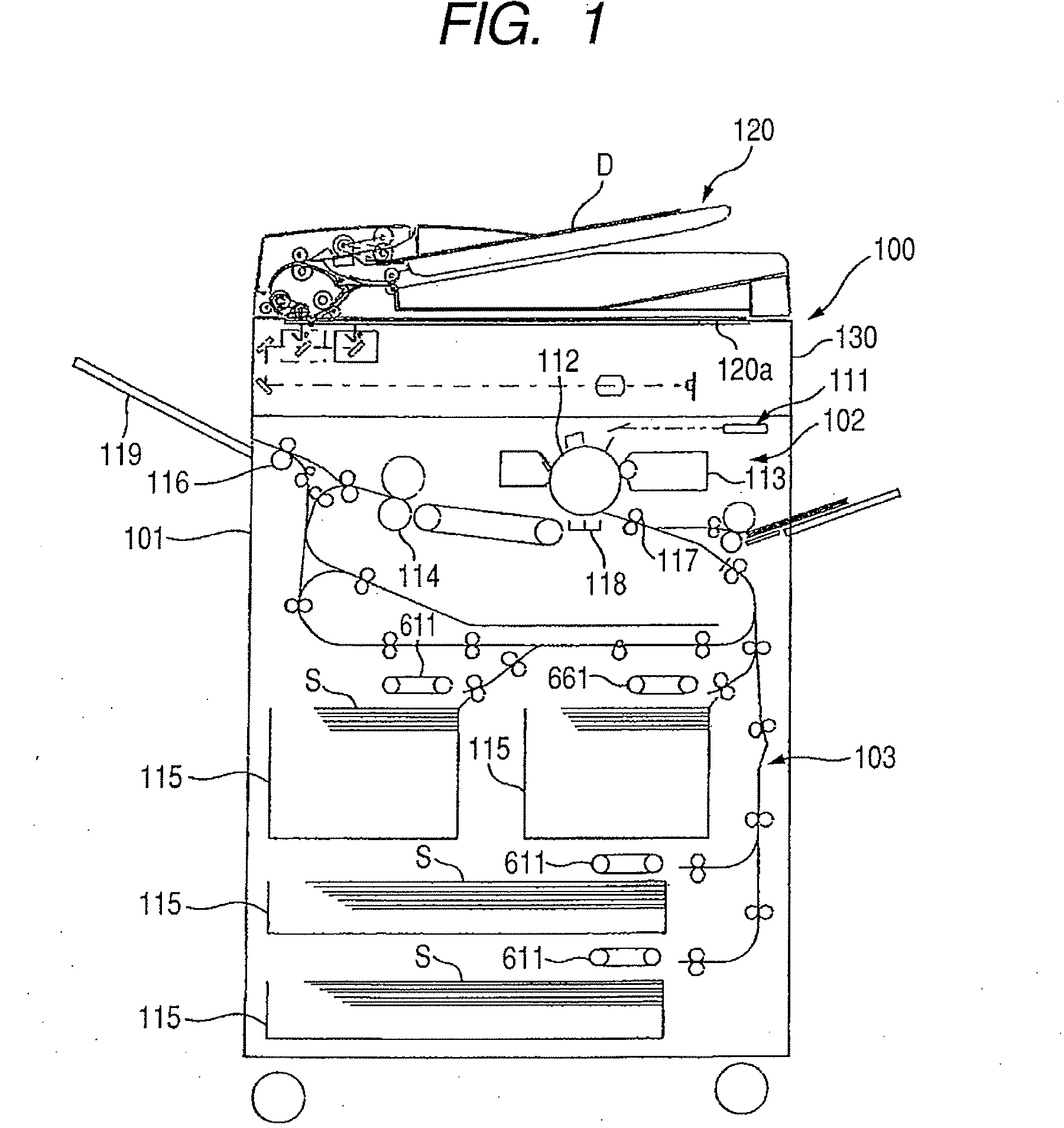
[0050]FIG. 1 is a diagram illustrating a schematic construction of a printer as an example of an image forming apparatus having a sheet feeding apparatus according to the embodiment of the invention.

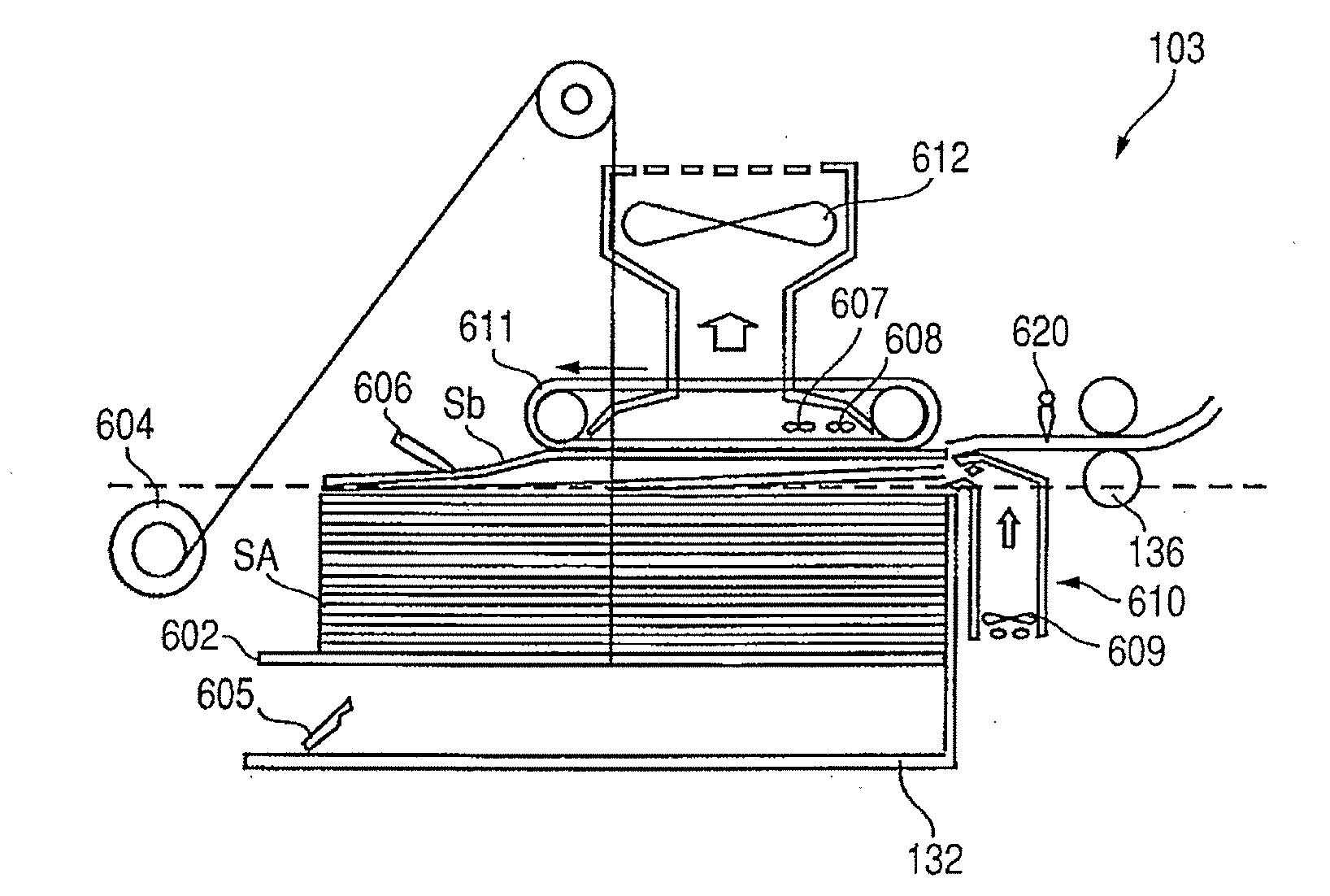
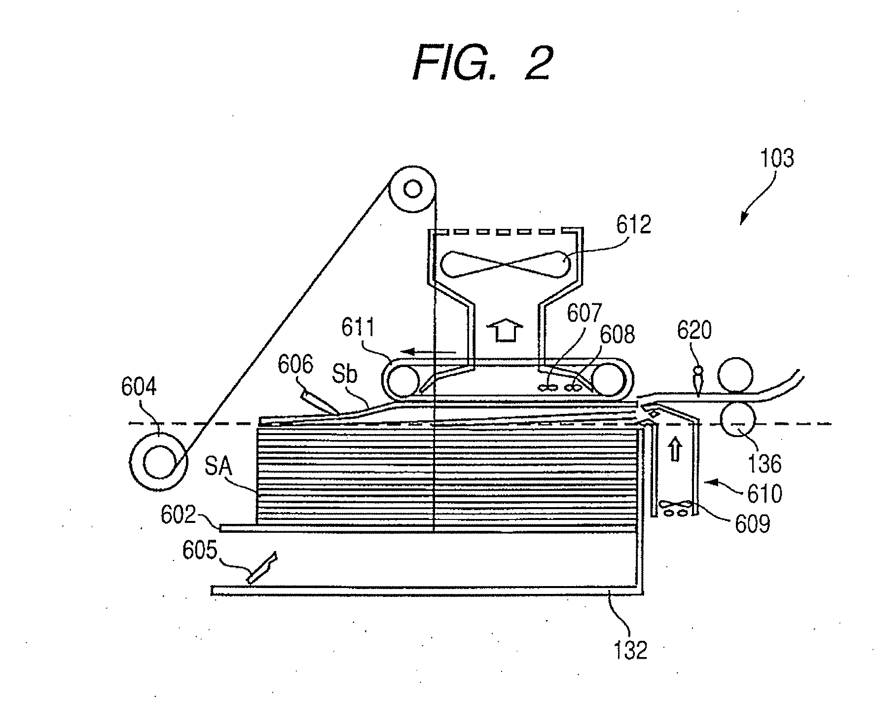
[0051]In FIG. 1, an image reading unit 130 for reading an original document (hereinbelow, simply referred to as an original) D put on platen glass 120a as a document setting base plate by an automatic document feeder (ADF) 120 is provided in an upper portion of a printer main body 101 of a printer 100. An image forming unit 102 and a sheet feeding apparatus 103 for feeding the sheet S to the image forming unit 102 is provided in a lower portion of the image reading unit 130. A photosensitive drum 112, a developing unit 113, a laser scanner unit 111, and the like are provided for the image forming unit 102. The sheet feeding apparatus 103 has a plurality of shee...


PUM


Abstract

A sheet feeding apparatus and an image forming apparatus which can certainly feed sheets without being influenced by an aging change of fan characteristics are provided. An air is blown to sheets stacked on a tray by an air blowing mechanism having a plurality of fans which are independently rotated, thereby loosening the sheets. Prior to starting the feeding of the sheet, rotational speeds of the fans of the air blowing mechanism are controlled so as to be set to target rotational speeds which have been preset every plural fans so that a wind pressure which can loosen the sheets in the driving state of all fans is obtained.

Description

BACKGROUND OF THE INVENTION[0001]1. Field of the Invention[0002]The present invention relates to an image forming apparatus having a sheet feeding apparatus for feeding sheets after the air was blown to the sheets and the sheets were loosened.[0003]2. Description of the Related Art[0004]Among conventional image forming apparatuses such as copying apparatus, printer, and the like, there is an apparatus having a sheet feeding apparatus for separating sheets stacked on a tray from the top sheet one by one and feeding them to an image forming unit.[0005]As such a sheet feeding apparatus, as disclosed in Japanese Patent Application Laid-Open No. H07-196187, there is an apparatus of a type in which the air is blown to a sheet bundle stacked on a tray, a plurality of sheets is floated and separated, and thereafter, the sheet is adsorbed to an adsorbing and conveying belt and fed.[0006]FIG. 20 is a cross sectional view illustrating an example of a sheet feeding apparatus with such a constru...

Claims


Application Information

Patent Timeline
Patent Type & Authority Applications(United States)
IPC IPC(8): B65H5/22
CPCB65H3/48B65H2406/121B65H2515/212B65H2515/342B65H2220/09B65H2220/02B65H2515/20B65H2515/34
Inventor MATSUMOTO, YUZO
Owner CANON KK
Why Eureka
Try Eureka