

Conductor Having Two Frequency-Selective Surfaces
a technology of frequency-selective surfaces and capacitors, applied in the field of antennae, can solve the problems of large size and mechanical complexity of the antenna system capable of providing independent operations in different directions
- Summary
- Abstract
- Description
- Claims
- Application Information
AI Technical Summary
Benefits of technology
Problems solved by technology
Method used
Image

Examples
Embodiment Construction
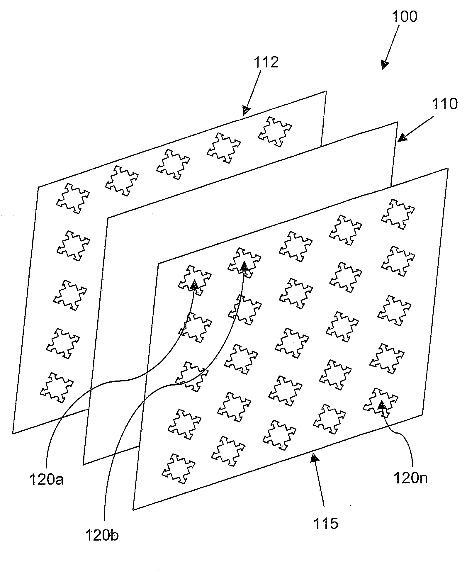
[0013]With reference now to the drawings, and in particular to FIG. 1, there is depicted a diagram of an antenna reflector system having multiple frequency-selective surfaces (FSSs), in accordance with a preferred embodiment of the invention. As shown, a two-sided antenna reflector 100 includes a perfect electrical conductor (PEC) 110 located between a FSS 112 and a FSS 115. As utilized herein, a PEC is defined as any conducting plane that carries surface current with minimal resistance, and a FSS is defined any surface that provides the correct wave impedance, through any means, to reflect electromagnetic waves, such that a reflected wave is substantially in phase with an incoming wave. A metallization layer in a printed wiring board is an example of a PEC. In FIG. 1, an FSS, such as FSS 115, is accomplished with a shield plane (e.g., a metallization layer) that is patterned with holes, such as multiple holes 120a-120n, to form a mesh.
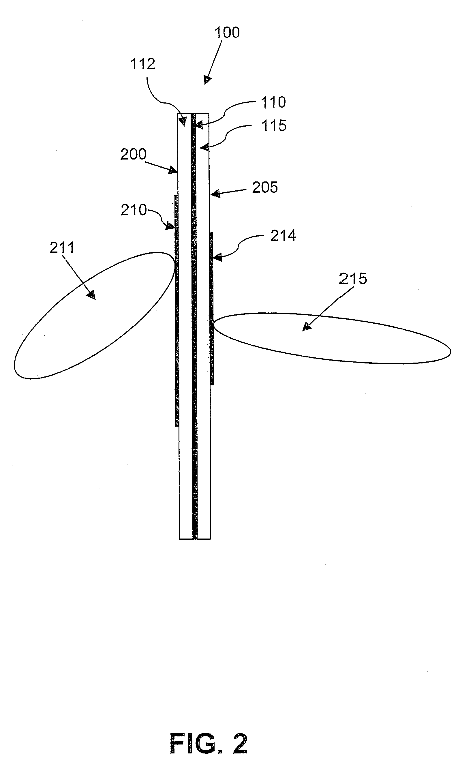
[0014]With reference now to FIG. 2, there is de...
PUM
 Abstract
Description
Claims
Application Information