Golf club head

Inactive Publication Date: 2009-04-23
O TA PRECISION IND
View PDF10 Cites 4 Cited by
  • Summary
  • Abstract
  • Description
  • Claims
  • Application Information

AI Technical Summary

Benefits of technology

[0005]Therefore, the object of the present invention is to provide a golf club head which possesses a lightweight property, superior weight distribution, and improved striking stability.

Problems solved by technology

However, since the size of the shock-absorbing layer 12 is substantially equal to that of the striking portion 11, the overall weight of the golf club head 1 is relatively heavy, which in turn increases the striking load of the player and reduces the striking controllability.

Method used


Image

  • Golf club head
  • Golf club head
  • Golf club head

Examples


Embodiment Construction

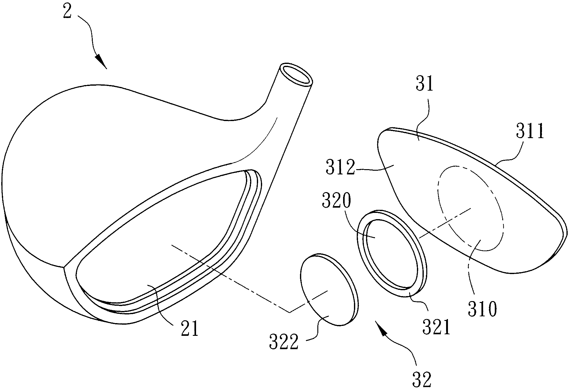
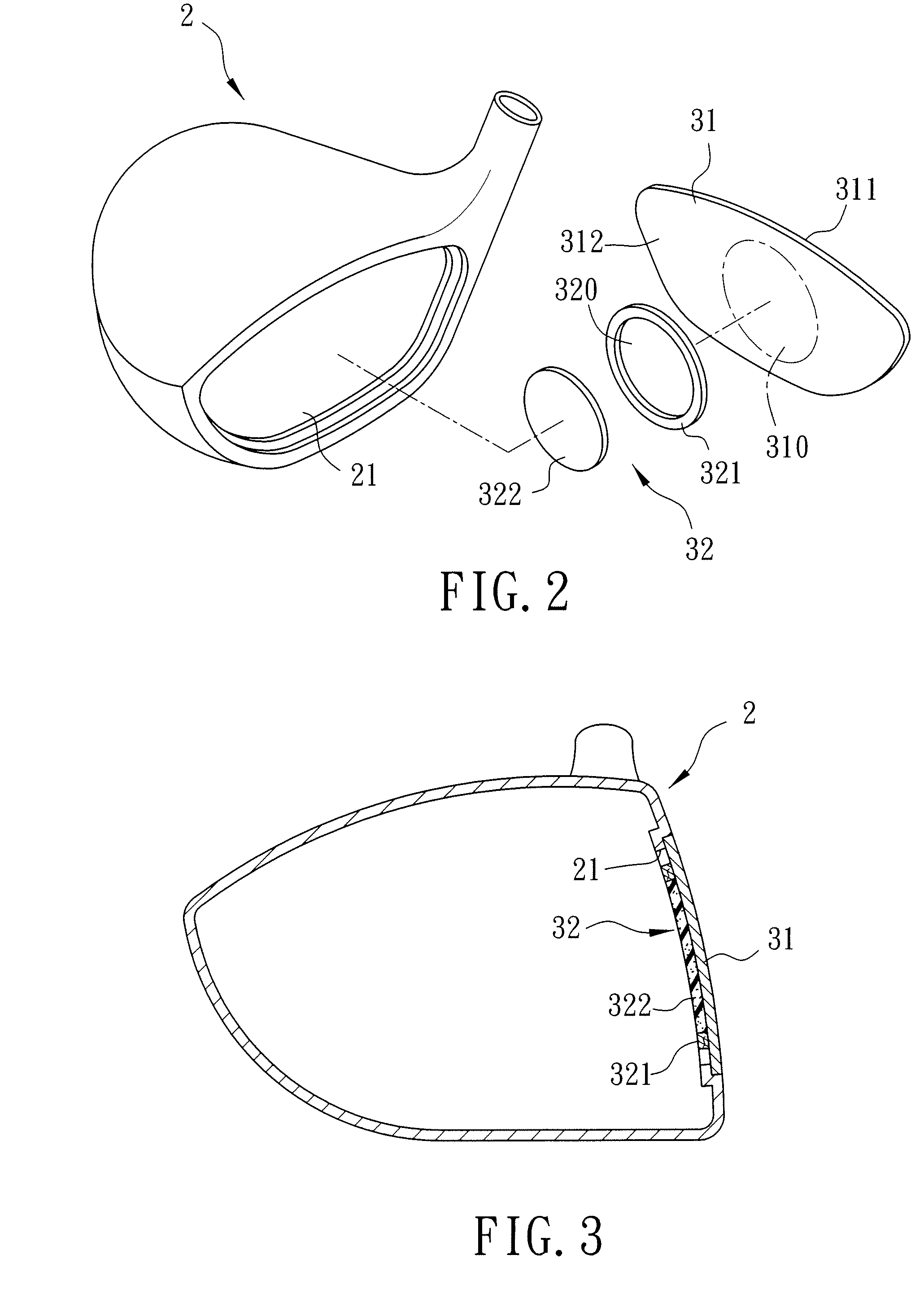
[0011]Referring to FIGS. 2 and 3, the preferred embodiment of a golf club head according to this invention is shown to include a hollow head body 2, a striking plate 31, and a shock absorber 32.

[0012]The hollow head body 2 has a front opening 21.

[0013]The striking plate 31 covers the front opening 21, and has a front face 311, a rear face 312, and a sweet spot 310. In the preferred embodiment, the striking plate 31 is made of a titanium alloy.

[0014]The shock absorber 32 is connected to the rear face 312 of the striking plate 31, corresponds in position to the sweet spot 310, and has a size smaller than that of the front opening 21 and substantially equal to an area of the sweet spot 310. The shockabsorber 32 includes a rim member 321 attached to the rear face 312 of the striking plate 31 and defining a receiving space 320, and a shock absorbing element 322 fitted into the receiving space 320. In the preferred embodiment, the rim member 321 is made of a carbon-fiber material, and the...


PUM


Abstract

A golf club head includes a hollow head body, a striking plate, and a shock absorber. The hollow head body has a front opening. The striking plate covers the front opening, and has a front face, a rear face, and a sweet spot. The shock absorber is connected to the rear face of the striking plate, corresponds in position to the sweet spot, and has a size smaller than that of the front opening and substantially equal to an area of the sweet spot.

Description

BACKGROUND OF THE INVENTION[0001]1. Field of the Invention[0002]The invention relates to a golf club head, more particularly to a golf club head with a lightweight property, superior weight distribution, and improved striking stability.[0003]2. Description of the Related Art[0004]Referring to FIG. 1, a conventional golf club head 1 includes a striking portion 11 made of a metal having a high coefficient of restitution, and a shock-absorbing layer 12 connected to a rear face of the striking portion 11 and having a size substantially equal to that of the striking portion 11 so as to raise the rebound and shock-absorbing capabilities of the golf club head. However, since the size of the shock-absorbing layer 12 is substantially equal to that of the striking portion 11, the overall weight of the golf club head 1 is relatively heavy, which in turn increases the striking load of the player and reduces the striking controllability. Moreover, since the striking portion 11 is provided with t...

Claims


Application Information

Patent Timeline
IPC IPC(8): A63B53/04
CPCA63B53/0466A63B59/0092A63B2053/042A63B2209/00A63B2209/02A63B2053/0416A63B60/54A63B53/042A63B53/0416
Inventor LIN, CHON-CHENHU, SHUN-FUHSU, YEN-CHI
Owner O TA PRECISION IND
Why Eureka
Try Eureka