Optical Absolute Rotary Encoder

a rotary encoder and absolute technology, applied in the field of absolute rotary encoders, can solve the problems of erroneously reading absolute position information, difficulty in miniaturizing the entire rotary encoder, and difficulty in miniaturizing the entire rotary encoder, and achieve the effect of effective and properly guided configuration and simple configuration

Inactive Publication Date: 2009-04-30
STANLEY ELECTRIC CO LTD
View PDF6 Cites 27 Cited by
  • Summary
  • Abstract
  • Description
  • Claims
  • Application Information

AI Technical Summary

Benefits of technology

[0041]In this instance, since the light incident surface of the light guide unit can collimate the incident light, there is no need to have any additional optical parts such as a collimator lens for collimating output light when the light emit...

Problems solved by technology

This may complicate the structure for electrically connecting the parts with each other and for optical arrangement, resulting in difficulty in miniaturizing the entire rotary encoder.
This may result in erroneously reading ...

Method used


Image

  • Optical Absolute Rotary Encoder
  • Optical Absolute Rotary Encoder
  • Optical Absolute Rotary Encoder

Examples


Embodiment Construction

[0061]A description will now be given of exemplary embodiments that are constructed in accordance with principles of the presently disclosed subject matter with reference to the accompanying drawings. The presently disclosed subject matter, however, is not limited to these exemplary embodiments.

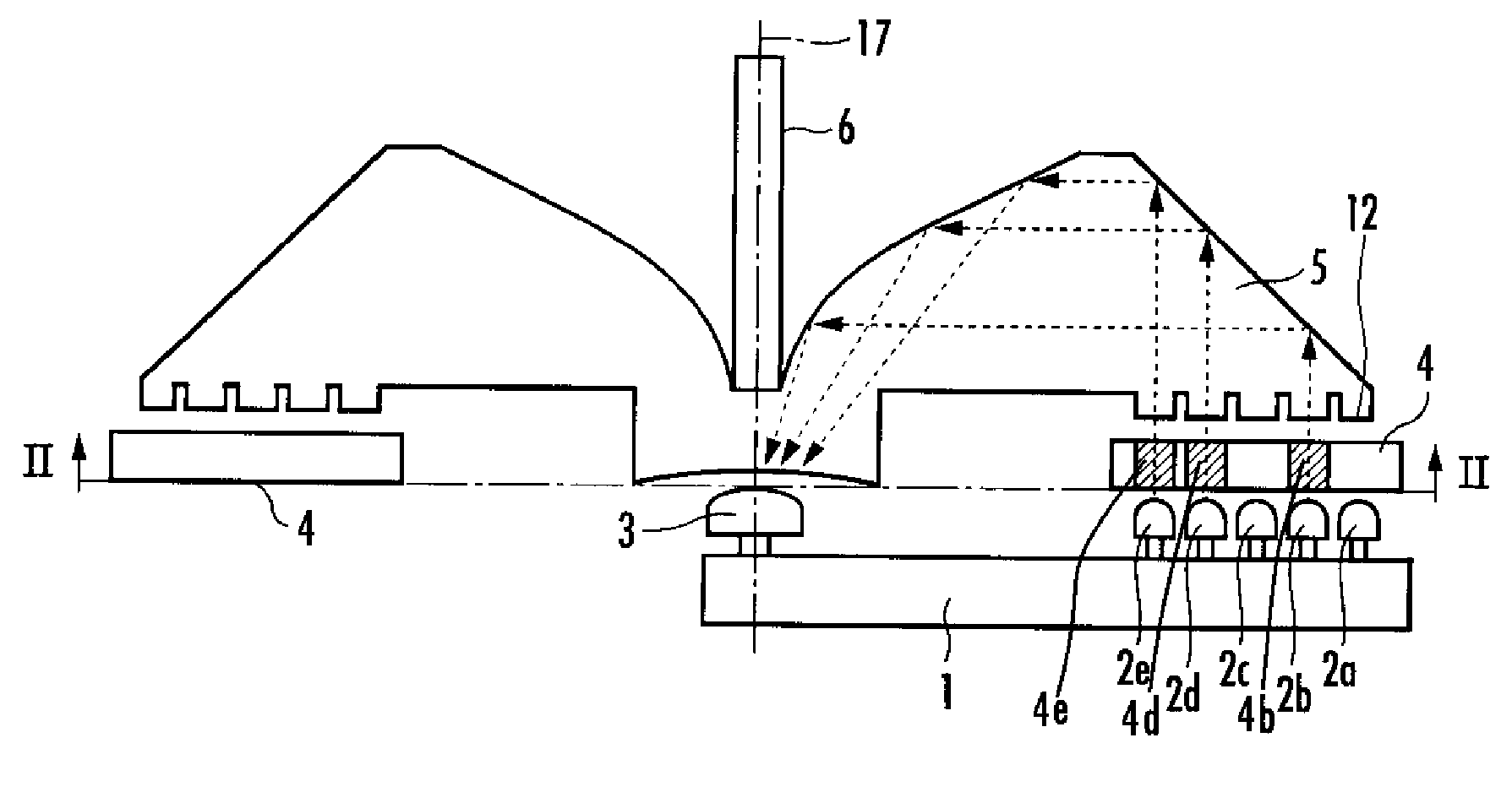
[0062]FIG. 4 shows a cross-sectional view of an optical absolute rotary encoder made in accordance with principles of the presently disclosed subject matter. The optical absolute rotary encoder can include a plurality of light emitting devices 2a to 2e (five light emitting devices in this exemplary embodiment), a single light receiving device 3, a rotary disk 4, and a rotary light guide disk 5. The plurality of light emitting devices 2a to 2e can project light onto the rotary disk 4. Here, the rotary disk 4 is an optical scale having an absolute pattern. The rotary light guide disk 5 serving as a light guide unit can guide the light passing through the rotary disk 4 to the light receiving dev...


PUM


Abstract

An optical absolute rotary encoder can have a simple and small structure, for determining the absolute values of rotational positions with high accuracy. The encoder can include an optical scale having an absolute pattern representing a code corresponding to a single absolute value using a transmitting area and/or an intercepting area. A light emitting unit can be arranged at one side with respect to the optical scale, and configured to project light on the optical scale. A light receiving unit can be arranged at the same side as the light emitting unit, can configured to receive light passing through the transmitting area of the optical scale. A light guide unit can be provided and configured to guide the light from the light emitting unit to the light receiving unit. The optical scale and the light emitting unit can rotate relative to each other about an axis of rotation, and the light receiving unit can be disposed on the axis of rotation.

Description

[0001]This application claims the priority benefit under 35 U.S.C. § 119 of Japanese Patent Application No. 2006-265259 filed on Sep. 28, 2006 and Japanese Patent Application No. 2006-315992 filed on Nov. 22, 2006, which are hereby incorporated in their entirety by reference.BACKGROUND[0002]1. Technical Field[0003]The disclosed subject matter relates to an absolute rotary encoder, and in particular, to an optical absolute rotary encoder for detecting a rotational position as an absolute position.[0004]2. Description of the Related Art[0005]Known optical absolute rotary encoders disclosed in, for example, Japanese Patent Application Laid-Open No. Hei 06-347292 can detect a rotational position as an absolute value based on transmitted light from a light emitting device. One exemplary structure of a rotary encoder is shown in FIG. 1. The rotary encoder includes a light emitting device 102, a drive circuit 101 for driving the light emitting device 102, a collimator lens 103 for collimat...

Claims


Application Information

Patent Timeline
Owner STANLEY ELECTRIC CO LTD
Why Eureka
Try Eureka