Top cap

Active Publication Date: 2009-09-03
ORBIS CORP
View PDF24 Cites 3 Cited by
  • Summary
  • Abstract
  • Description
  • Claims
  • Application Information

AI Technical Summary

Benefits of technology

[0017]In accordance with yet another aspect of the invention, a top cap is provided that comprises a first upper surface configured to securely mate with any of a footprint of a first pall

Problems solved by technology

Otherwise, the upper system could become unstable and possibly injure someone below and/or damage

Method used


Image

  • Top cap
  • Top cap
  • Top cap

Examples


Embodiment Construction

[0059]While this invention is susceptible of embodiments in many different forms, there is shown in the drawings and will herein be described in detail preferred embodiments of the invention with the understanding that the present disclosure is to be considered as an exemplification of the principles of the invention and is not intended to limit the broad aspect of the invention to the embodiments illustrated.

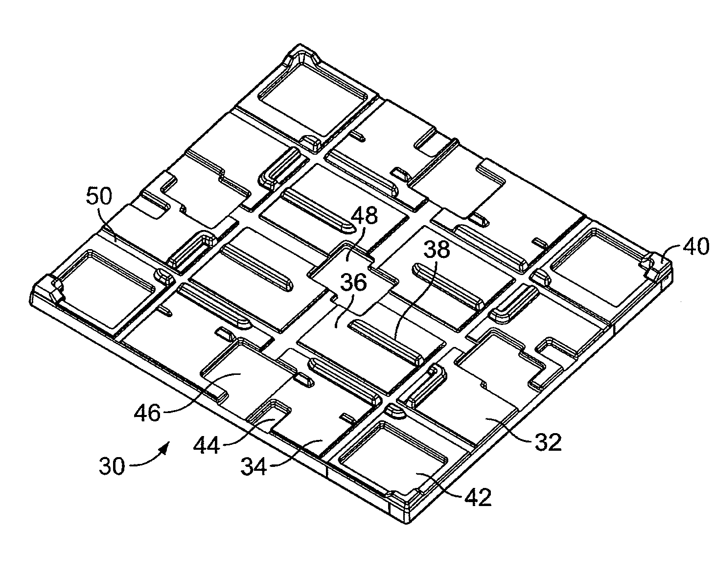
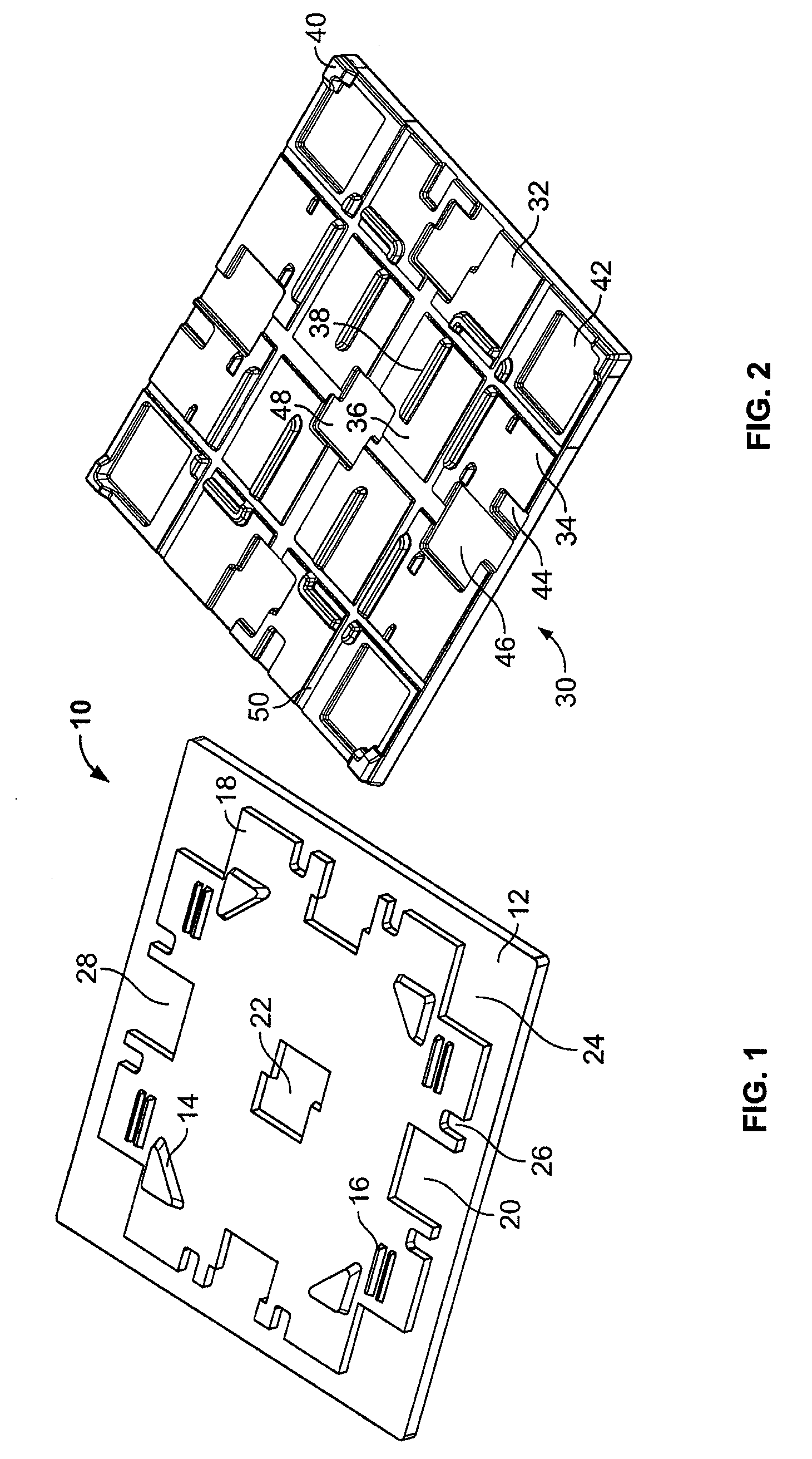
[0060]Referring to FIG. 1, a first top cap design 10 in accordance with the present invention is provided. The top cap 10 has a generally rectangular or square outline or shape (preferably dimensioned as 45×48 inches) and includes a top surface 12. The top cap 10 is preferably formed from a molded plastic.

[0061]The top surface 12 of the top cap 10 includes structure to mate with or securely support a variety of packaging systems that may be stacked on top of the top cap 10. In this embodiment, the top surface 12 includes a plurality of raised portions 14, 16, 18, which cooperat...


PUM


Abstract

A top cap designed to allow any of a pallet, a bulk bin and a metal rack, each having a different support configuration, or any of a nestable pallet and a bulk bin, to stack securely on an upper surface of the top cap. The top cap including a plurality of raised and/or indented portions on the upper surface configured to mate with a bottom surface of the pallet, bulk bin or metal rack. The top cap also being configured to allow other pallets, bulk bins, or metal racks to stack securely on the upper surface of the top cap. The top cap being formed from a molded plastic material.

Description

CROSS-REFERENCE TO RELATED APPLICATIONS[0001]The application for the present invention is being filed concurrently with U.S. Design patent application Ser. No. 29 / 304,294 [Attorney Docket No.: 52045-3202].FEDERALLY SPONSORED RESEARCH OR DEVELOPMENT[0002]Not Applicable.TECHNICAL FIELD[0003]The invention relates to a top cap having an upper surface configured to securely mate with the footprint of all of one or more pallet designs, one or more bulk bin designs and one or more metal rack designs; or all of one or more nestable pallet designs with one or more bulk bin designs and / or one more metal rack designs.BACKGROUND OF THE INVENTION[0004]Goods and other items are transported utilizing a variety of containers and other packaging or transportation systems. Such packaging or transportation systems can include pallets, bulk bins, metal racks, etc. In some instances, a top cap is utilized as part of one or more of these systems. The top cap allows for securing a second load of product o...

Claims


Application Information

Patent Timeline
IPC IPC(8): B65D19/00
CPCB65D19/38B65D2571/00055B65D2519/00338
Inventor BANIK, JOACHIM
Owner ORBIS CORP
Why Eureka
Try Eureka