

Ankle-clamping device for an inversion table
a technology of inversion table and clamping roller, which is applied in the direction of snap fasteners, gymnastic exercise, sport apparatus, etc., can solve the problems of inconvenient use of the clamping roller unit, and increasing the manufacturing time and cost of the entire inversion table b>1/b>, so as to achieve quick and easy assembly
- Summary
- Abstract
- Description
- Claims
- Application Information
AI Technical Summary
Benefits of technology
Problems solved by technology
Method used
Image

Examples
Embodiment Construction
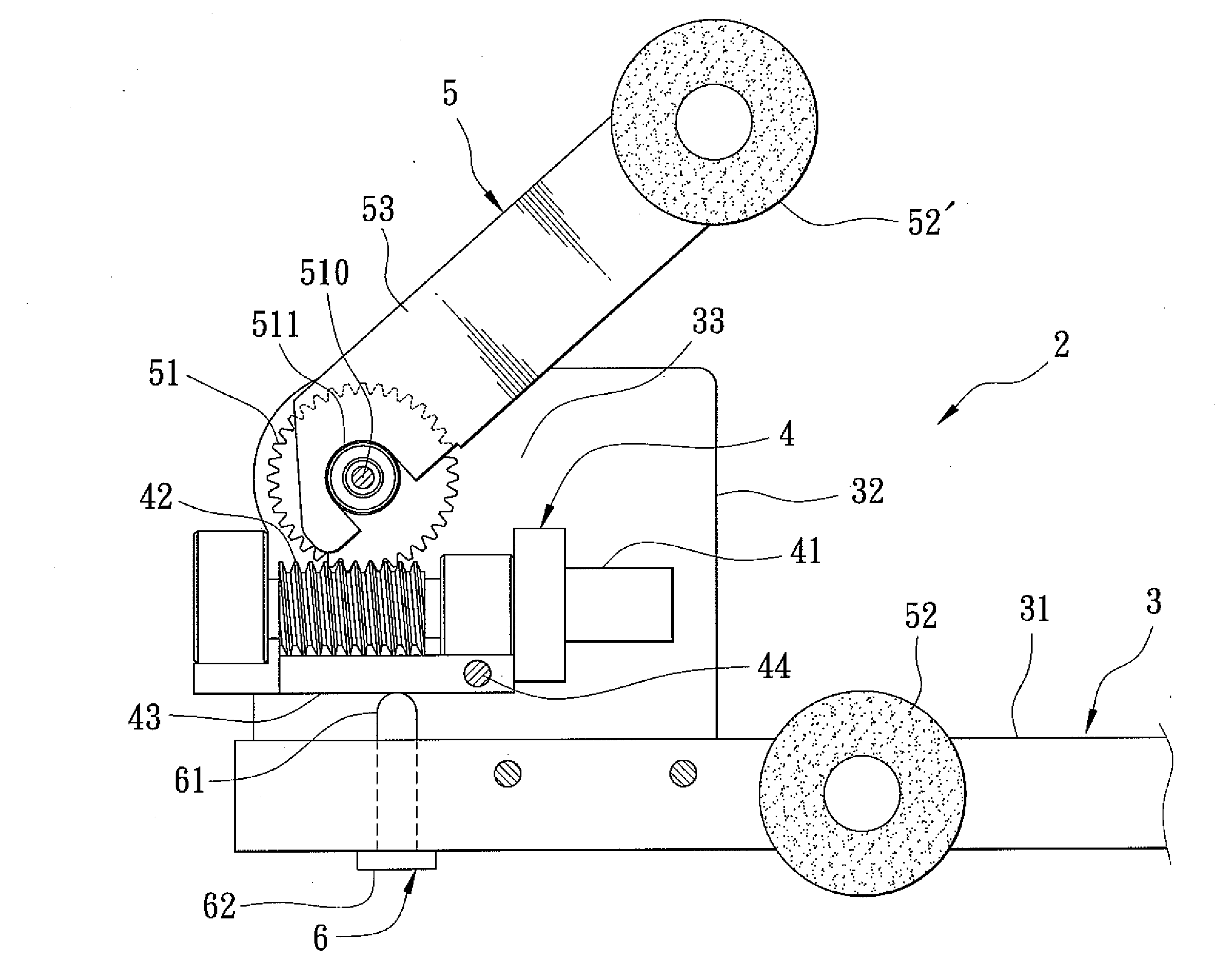
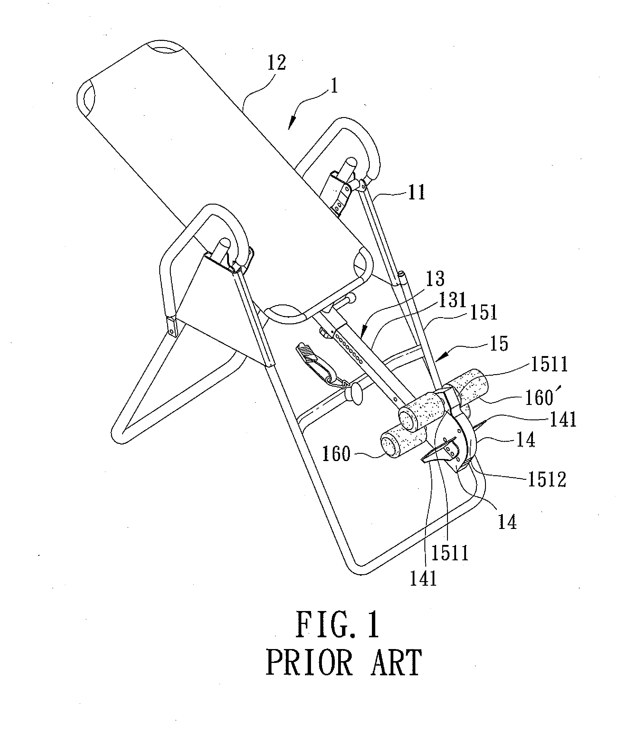
[0019]Referring to FIGS. 4 to 7, an ankle-clamping device 2 according to the preferred embodiment of the present invention is adapted to be incorporated in an inversion table 1 shown in FIG. 1, and is shown to comprise a clamp holder 3, a drive mechanism 4, a clamping roller unit 5, and a push member 6.
[0020]The clamp holder 3 includes an extendable bar 31, and two positioning plates 32 connected respectively to two opposite sides of the bar 31 at a front end thereof and cooperating with the bar 31 to define a receiving space 33.
[0021]The drive mechanism 4 includes a motor 41 disposed in the receiving space 33, a worm shaft 42 driven by the motor 41 to rotate, and a mounting seat 43 fulcrumed to and disposed between the positioning plates 32 through a pivot pin 44 for supporting the motor 41.
[0022]The clamping roller unit 5 includes a worm gear 51 connected rotatably to and disposed between the positioning plates 32 through a spindle 510 and meshing with the worm shaft 42, a lever 5...
PUM
 Abstract
Description
Claims
Application Information