Cryostat for superconducting mr magnets

Active Publication Date: 2010-01-28
SIEMENS HEALTHCARE GMBH
View PDF4 Cites 8 Cited by
  • Summary
  • Abstract
  • Description
  • Claims
  • Application Information

AI Technical Summary

Benefits of technology

[0017]The pressure sensor pipe is terminated with a pressure sensor pipe seal that breaks upon exceeding a predetermined pressure value, such that the tank can be vented via the pressure sensor pipe and the overpressure can be dissipated. The safety

Problems solved by technology

A particular danger is that the tower pipe of the magnet is completely sealed by air-ice droplets.
Such a sealing can occur due to operating error upon refilling with liquid helium or due to leaks in the system.
The seal withstands pressures up to several bars, such that the danger ex

Method used


Image

  • Cryostat for superconducting mr magnets
  • Cryostat for superconducting mr magnets
  • Cryostat for superconducting mr magnets

Examples


Embodiment Construction

[0021]The drawings are not to scale. Identical or identically operating elements are provided with the same reference characters insofar as it is not noted otherwise.

[0022]The invention assumes a bath cryostat. In a bath cryostat, the magnet coil to be cooled is surrounded by coolant. Liquid helium with a boiling point of −268.93° C. or 4.2 Kelvin serves as a coolant. The tank with the magnet coil is normally surrounded with two thermal shields for better thermal insulation.

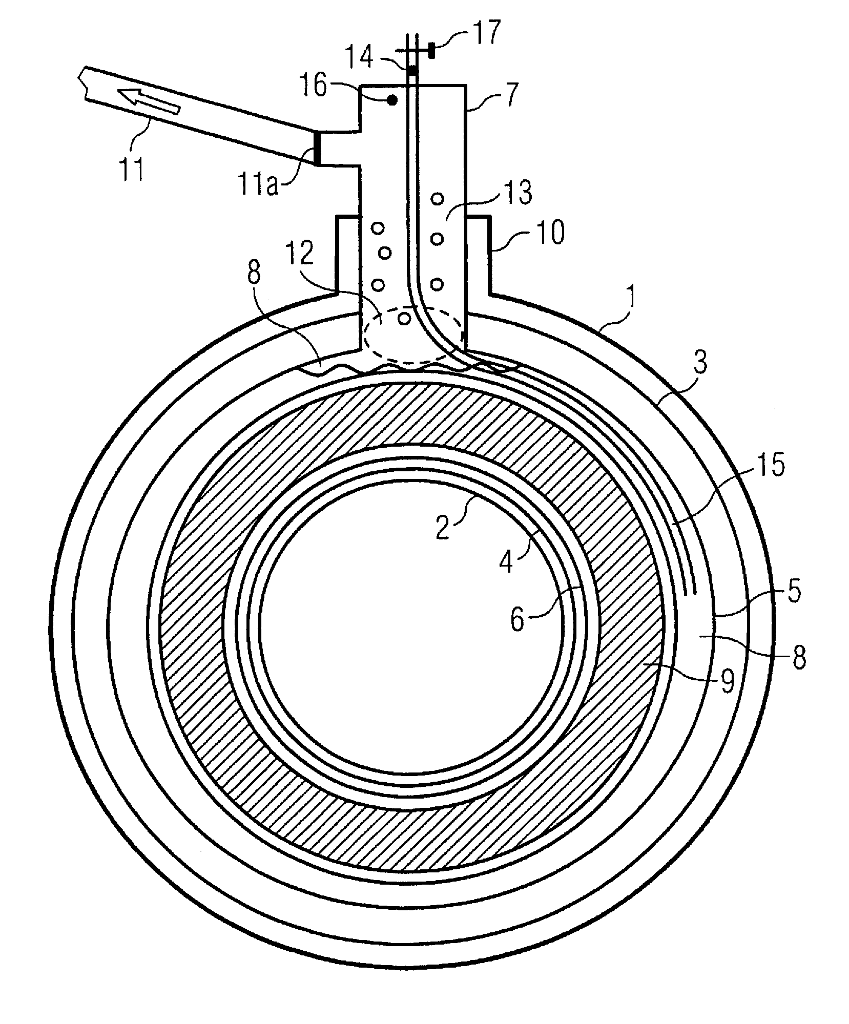
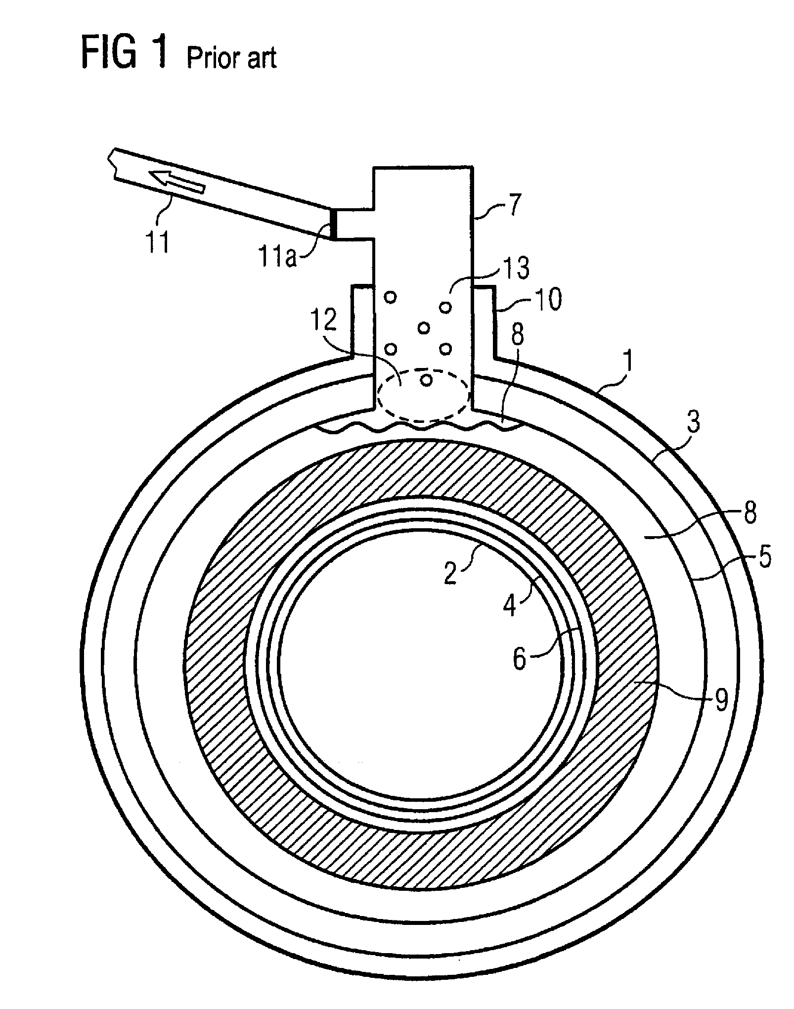
[0023]A schematic cross section through a cryostat for a superconducting magnet is shown in FIG. 1. The cryostat comprises a magnet housing with an outer surface 1 and an inner surface 2. Such a cryostat with superconducting magnet is used, for example, in an MRT apparatus for the generation of the basic magnetic field; the patient (not shown) then lies in the inner chamber that is defined by the inner surface 2 of the housing.

[0024]The conductor coils 9 generating the magnetic field are merely schematically indi...


PUM


Abstract

A cryostat has a tank for accommodation of a coolant and at least one superconducting magnet coil to generate a magnetic field. The tank has on a top side at least one tower pipe for filling the coolant and/or for venting vaporized coolant. In order to immediately indicate if and when sealing of filling pipes and discharging pipes with (for example) ice has occurred, a pressure sensor is connected via a pressure sensor pipe with the inside of the tank.

Description

BACKGROUND OF THE INVENTION[0001]1. Field of the Invention[0002]The present invention concerns a cryostat for an MR magnet for medical magnetic resonance (MR) imaging.[0003]2. Description of the Prior Art[0004]Superconducting magnetic coils are used in medical imaging in magnetic resonance tomography (MRT) apparatuses. The superconducting magnetic coils are cooled with liquid helium. If the superconducting magnet coils are suddenly transitioned into the normally-conducting state (“quench”), the energy of the magnetic field is transduced into heat. The liquid helium is thereby vaporized and large quantities of cold helium gas must be safely conducted to the atmosphere. For this purpose, an opening is provided on the top of the tank in which the magnet is located. A structure known as the tower (or turret) extends above the opening, with a tower pipe that serves for filling the tank with liquid helium. The tower pipe transitions into the quench pipe. The diameter of the quench pipe de...

Claims


Application Information

Patent Timeline
IPC IPC(8): H01F6/06
CPCF25B45/00F25D3/10F25B2700/19
Inventor BITTNER, GERHARD
Owner SIEMENS HEALTHCARE GMBH
Why Eureka
Try Eureka