Suture Passing Device with Controllable Suture Retrieval Mechanism

a suture passing device and controllable technology, applied in the field of arthroscopic surgery, can solve the problems of ineffective hook configuration, no practical and effective mechanism to retrieve the suture, and the inability to relocate the suture passed

Inactive Publication Date: 2010-10-07
PARK SANGDO
View PDF4 Cites 18 Cited by
  • Summary
  • Abstract
  • Description
  • Claims
  • Application Information

AI Technical Summary

Benefits of technology

[0007]The current invention is a modification to suture passing devices which employ a configuration of having upper and lower jaws to both grasp a tissue and deploy a suture loaded needle from one of the jaws. The current invention allows for an operator-controlled means to grasp the passed suture with a mechanism located within the jaw opposite the side of needle deployment. A sliding block located within the jaw opposite the side of needle deployment is controllable by the operator near the handle of the device and it...

Problems solved by technology

However, to date, there exists no practical and effective mechanism to retrieve the suture once it is passed through the tissue with the very same device.
In such an instance, the hook configuration is ineffective.
The problem with ...

Method used


Image

  • Suture Passing Device with Controllable Suture Retrieval Mechanism
  • Suture Passing Device with Controllable Suture Retrieval Mechanism
  • Suture Passing Device with Controllable Suture Retrieval Mechanism

Examples


Embodiment Construction

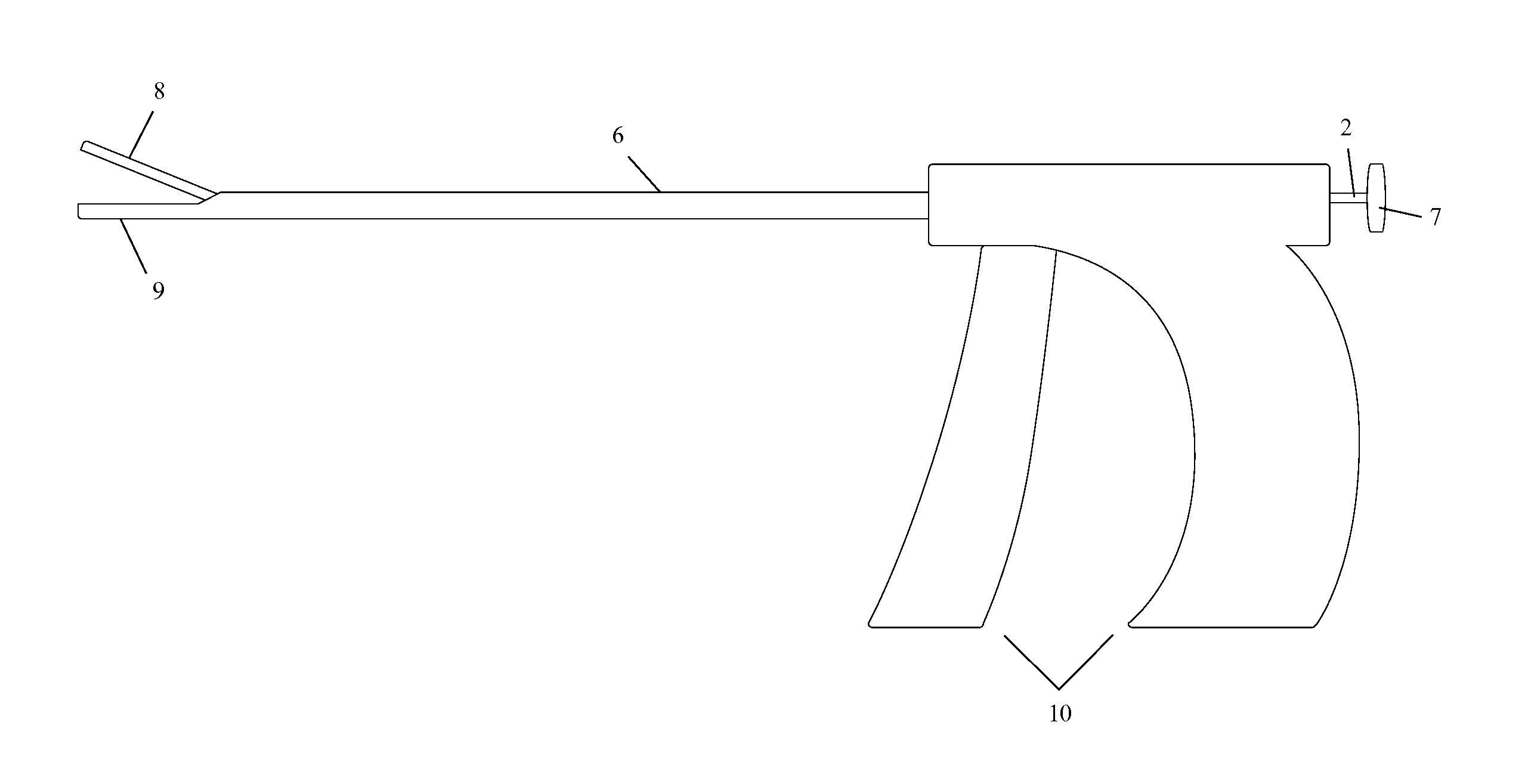
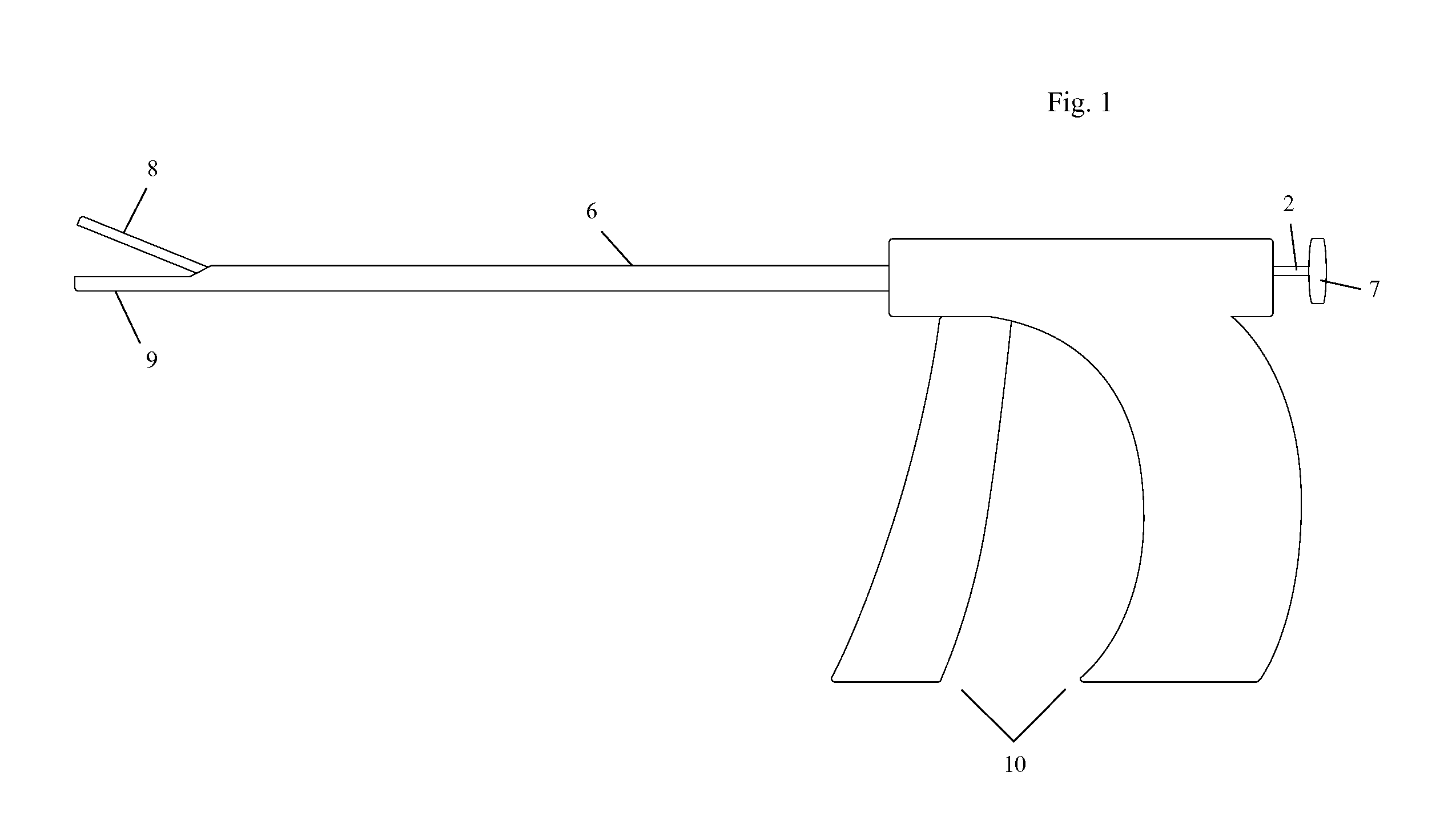
[0013]FIG. 1 is a schematic view of the suture passing device. It is comprised of upper jaw 8, lower jaw 9, body portion 6, handle portion 10, and a control member 7. The lower jaw 9 is the side from which deployment of suture loaded needle occurs. The upper jaw 8 is opposite lower jaw 9, and it is the side containing the mechanism for grasping and retrieval of the suture.

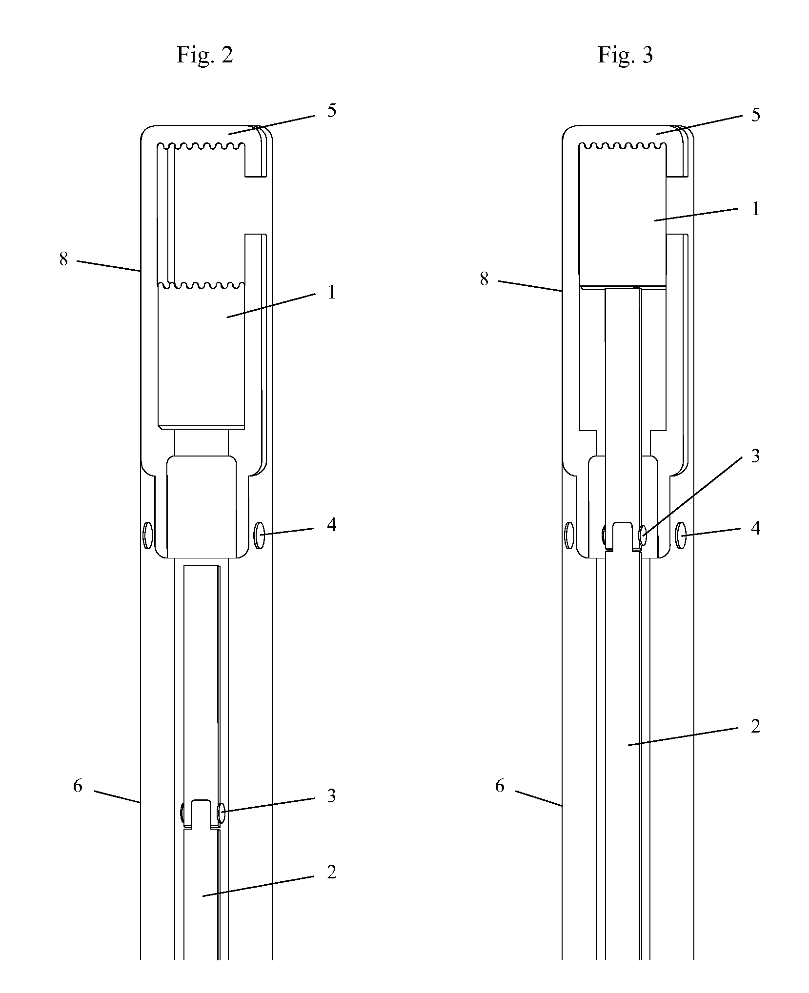
[0014]FIG. 2 is a view of the upper jaw 8 as seen from the top and a cross sectional view of the body portion 6 demonstrating sliding block 1 located within the upper jaw 8. A long rod 2 located within the body portion 6 comprises a hinge 3.

[0015]FIG. 3 is a view of the upper jaw 8 as seen from the top and a cross sectional view of the body portion 6 with the sliding block 1 engaged against the inner surface of the distal end of the jaw 5. This is the position required to grasp a suture passed through the upper jaw 8 and has been achieved by the operator pushing against the control member 7 in FIG. 1 which moves th...


PUM


Abstract

The current invention is a modification to suture passing devices which employ a configuration of having upper and lower jaws to both grasp a tissue and deploy a suture loaded needle from one of the jaws. The current invention allows for an operator-controlled means to grasp the passed suture with a mechanism located within the jaw opposite the side of needle deployment. A sliding block located within the jaw opposite the side of needle deployment is controllable by the operator near the handle of the device and provides movement of the sliding block against the inner surface of the distal end of the jaw to exert compression on the passed suture. This compression allows for grasping and retrieval of the passed suture.

Description

[0001]This application claims the benefit of U.S. Provisional Patent Application No. 61 / 166,732 filed on Apr. 4, 2009.BACKGROUND OF THE INVENTION[0002]1. Technical Field[0003]This device is of relevance to the field of arthroscopic surgery.[0004]2. Description of the Prior Art[0005]There have been several inventions which seek to facilitate the passage of suture through a tissue via arthroscopic means. The most effective and widely used of these inventions share the common configuration of being elongate in appearance and having at one end upper and lower jaws to both grasp tissue and pass a suture loaded needle, which is usually deployed from the lower jaw, and at the other end of the device, a handle with means to control the action of the jaw and passage of the needle. However, to date, there exists no practical and effective mechanism to retrieve the suture once it is passed through the tissue with the very same device. A hook-like configuration on the jaw opposite the jaw with ...

Claims


Application Information

Patent Timeline
IPC IPC(8): A61B17/04
CPCA61B17/0469A61B17/29A61B17/062
Inventor PARK, SANGDO
Owner PARK SANGDO
Why Eureka
Try Eureka