Roof Spoiler

a technology of roof spoiler and roof plate, which is applied in the field of roof spoiler, can solve the problems of roof damage, roof shingles peeling up and lifting themselves off the roof, and affecting the stability of the deployed position of the roof plate, so as to facilitate the stability of the deployed position

Inactive Publication Date: 2010-11-11
WINDTRIPPER CORP
View PDF16 Cites 11 Cited by
  • Summary
  • Abstract
  • Description
  • Claims
  • Application Information

AI Technical Summary

Benefits of technology

[0010]In one embodiment, the spoiler is L-shaped to facilitate its stability in the deployed position. The two members that comprise the L-shape may be of equal length, or may be of different lengths, as required.

Problems solved by technology

One of the worst types of structural damage that can befall a building is roof damage.
In these cases, damage to the roof often leads to tremendous damage to the rest of the building, as a result of structural damage, and damage caused by the elements, such as rain or snow.
First, the wind, when blowing in a certain direction, can flow between the roof shingles and the underlying substrate.
This air flow can cause the roof shingles to peel up and lift themselves off the roof.
The removal of these shingles leaves the exposed roof susceptible to water, which can now enter through the area that is no longer protected by the missing shingles.
A second type of damage is caused by the effect of high speed attached flow over the surface of the roof.
This causes uplift on part or all of the roof structure, thereby exerting an upward force on the roof.
This force not only causes the shingles to lift from the roof, but can also cause the roof to pull away from the joists to which it is attached.
As the air flow travels along the surface of the roof, this vertical barrier presents an obstacle to its continued flow.
As a result, the wind must travel over the barrier, which causes the air flow to become turbulent.
Up to now, no roof spoilers have enjoyed commercial success or gained widespread use.
This lack of success is probably due to a number of reasons, including unattractive appearance (e.g., due to poor aesthetic design or location on roof surface), poor performance (e.g., due to product design, operation or location), costs, complexity of installation, etc.

Method used


Image

  • Roof Spoiler
  • Roof Spoiler
  • Roof Spoiler

Examples


Embodiment Construction

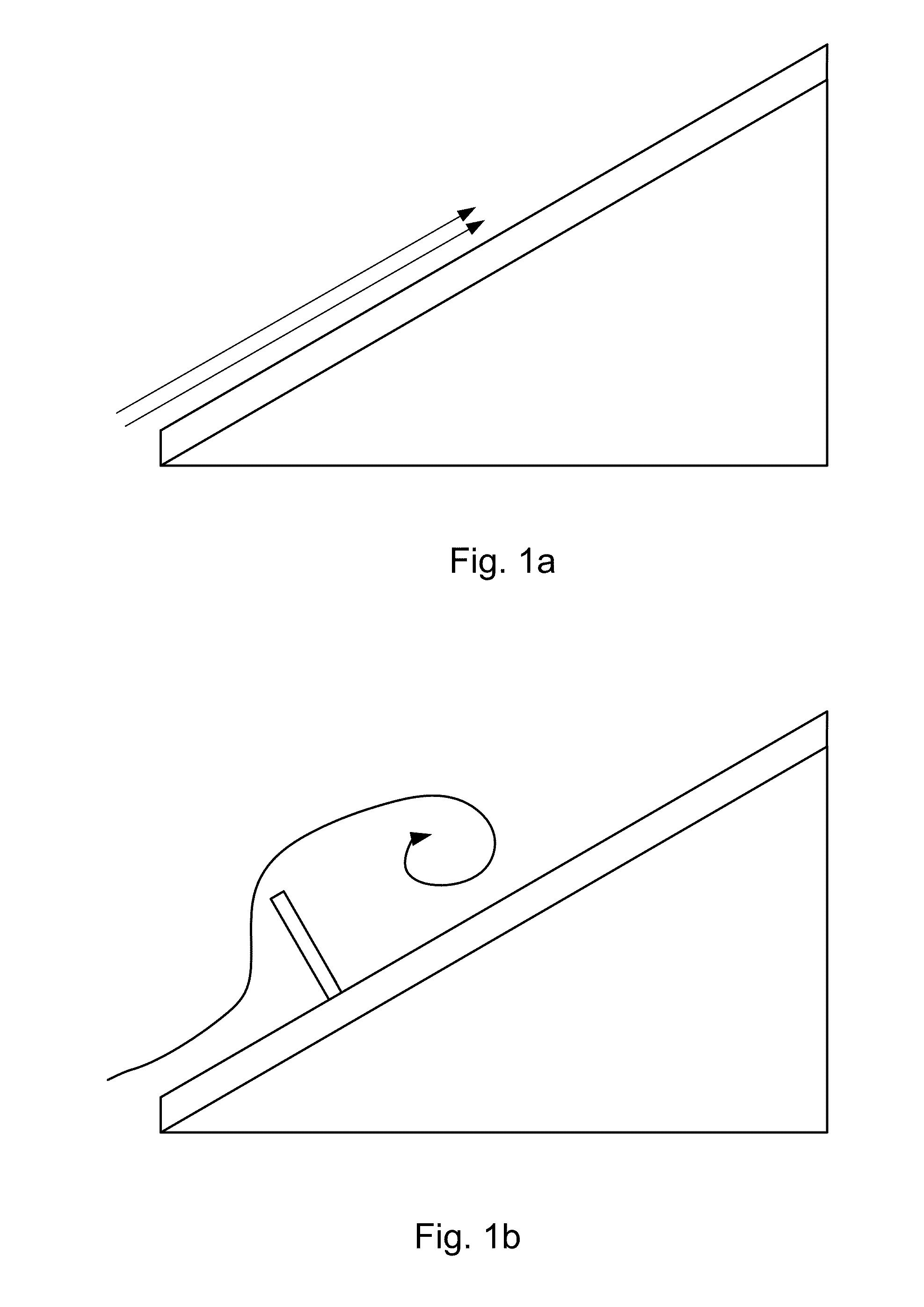
[0032]A roof spoiler is intended to present an obstacle to attached flow during high (e.g., hurricane-force) winds. One way to present such an obstacle is to introduce a vertical, or substantially vertical member that interrupts that air flow. In other embodiments, the obstacle may not be vertical, but rather orthogonal to the roof surface, as shown in FIG. 1b. However, as mentioned above, a vertical member attached to the roof surface is unsightly and not likely to be adopted.

[0033]To improve the aesthetics of a roof spoiler, it is preferable that the spoiler has at least two operating positions; a deployed position, where it acts as an obstruction as described above, and a stowed position, where the spoiler should be relatively non-intrusive and barely visible to passersby.

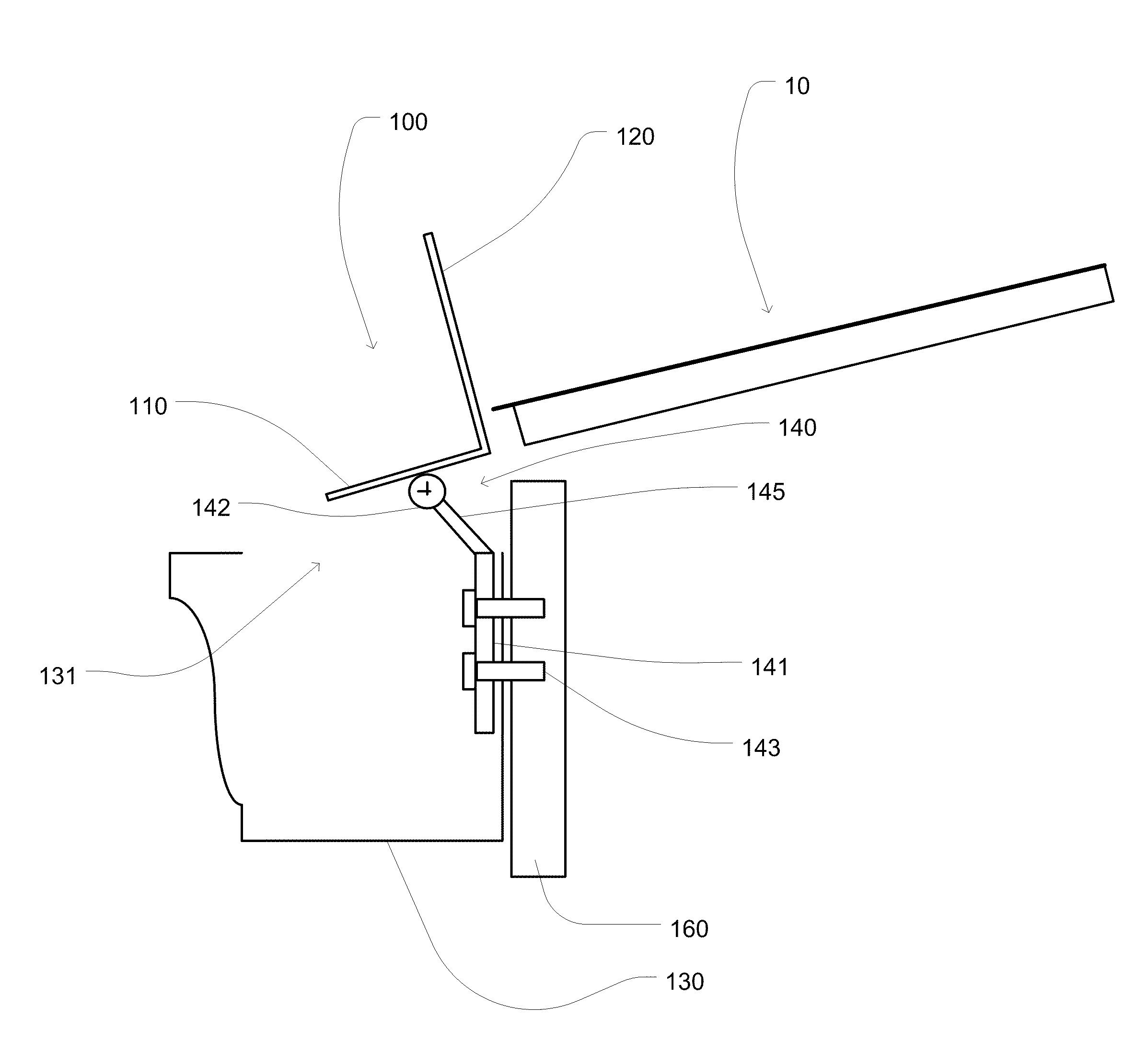
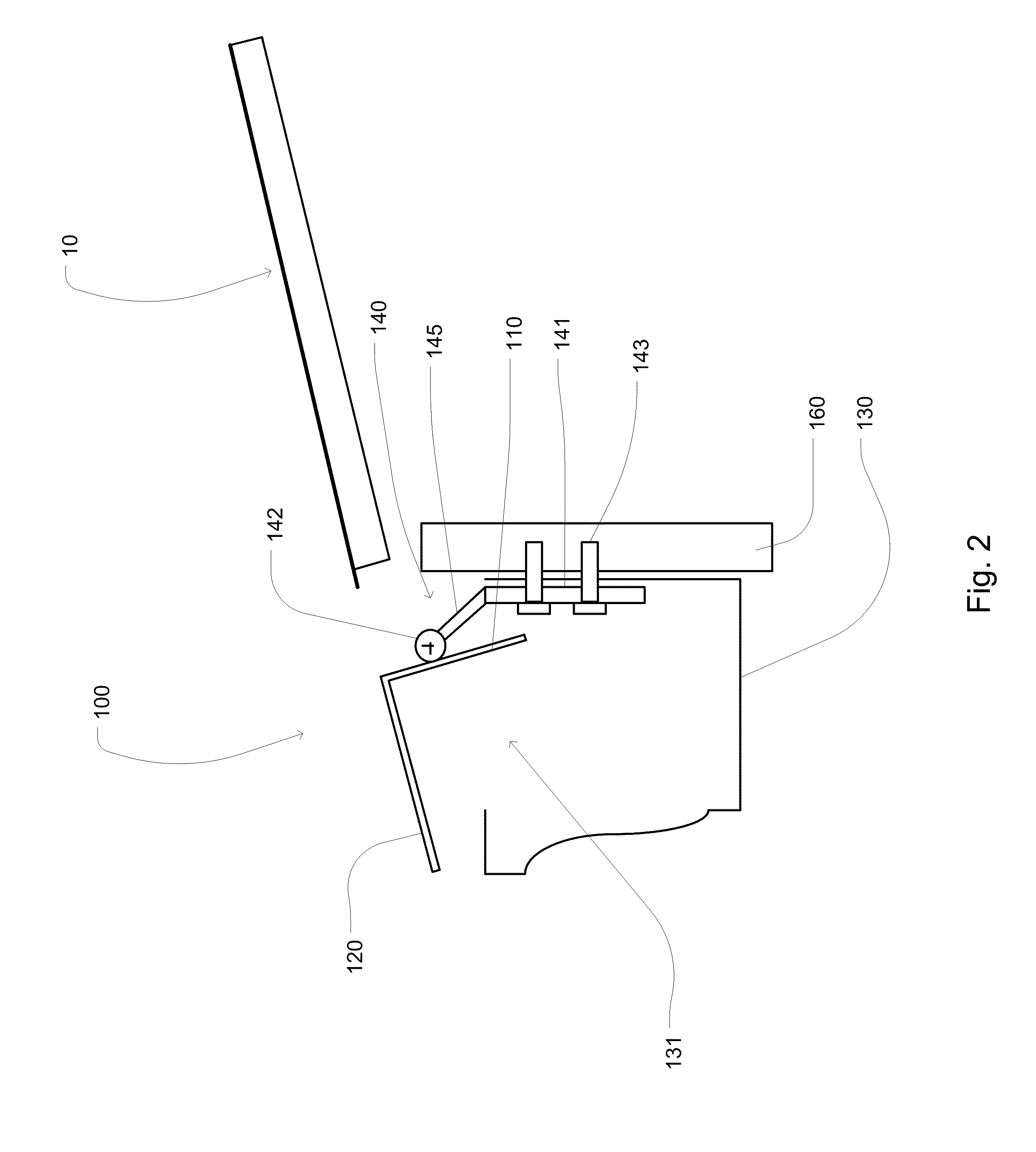
[0034]One embodiment of such a roof spoiler is depicted in FIG. 2, which shows a cross-section of a first embodiment of the roof spoiler in the stowed position. The roof spoiler 100 is preferably L-shaped, with ...


PUM


Abstract

Disclosed is a roof spoiler that effectively disrupts the attached flow of wind upon a roof surface. This spoiler has a stowed position, whereby it is almost completely out of the view of passersby. It also has a deployed position, wherein a barrier is projected vertically, or substantially vertically, so as to disrupt the flow of air over the roof surface. This spoiler utilizes a hinged design to move between these two positions. The spoiler is specially designed to operate in conjunction with a gutter mounted along the leading edge of the roof. In the stowed position, a portion of the spoiler covers the open gutter. In one embodiment, the spoiler is L-shaped to facilitate its stability in the deployed position.

Description

FIELD OF THE INVENTION[0001]The present invention relates to roofing systems. More particularly, it relates to an apparatus and a method for reducing wind damage to a roof.BACKGROUND OF THE INVENTION[0002]One of the worst types of structural damage that can befall a building is roof damage. The devastation caused by high winds, hurricanes, tornados and the like is depicted by the media, often by focusing on the damage done to homes, especially to the roofs of those homes. In these cases, damage to the roof often leads to tremendous damage to the rest of the building, as a result of structural damage, and damage caused by the elements, such as rain or snow.[0003]The roof of a building serves a number of purposes. First, it protects the interior of the building from the elements, such as rain, snow and hail. It also serves as an important structural component of the building, often linking the walls together, and adding strength to the building.[0004]Wind causes several different type...

Claims


Application Information

Patent Timeline
Patent Type & Authority Applications(United States)
IPC IPC(8): E04D13/00E04H9/14E04B1/38
CPCE04D13/00
Inventor KAISER, BRUCE A.OLDHAM, JAMES R.DEMORE, ANTHONY M.CARLSON, JESSE P.MORZANO, JENNIFER M.
Owner WINDTRIPPER CORP
Why Eureka
Try Eureka