

Over-voltage protection
- Summary
- Abstract
- Description
- Claims
- Application Information
AI Technical Summary
Benefits of technology
Problems solved by technology
Method used
Image

Examples
Embodiment Construction
[0032]The following detailed description of the invention refers to the accompanying drawings. The same reference numbers in different drawings identify the same or similar elements. Also, the following detailed description does not limit the invention. Instead, the scope of the invention is defined by the appended claims and equivalents.
Exemplary System
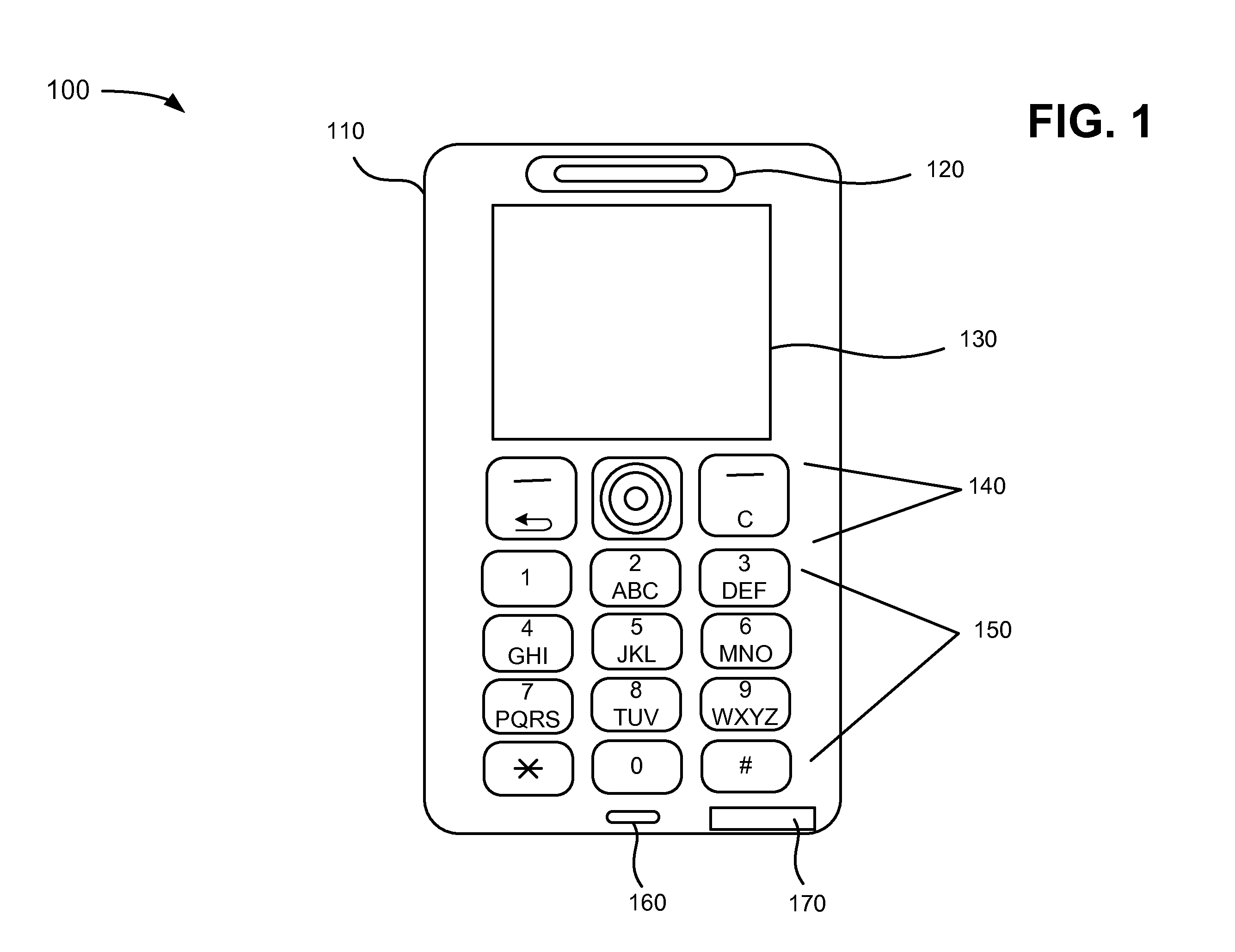
[0033]FIG. 1 is a diagram of an exemplary user device 100 which may be used in conjunction with devices, systems and methods described herein. In an exemplary implementation, user device 100 may be a mobile terminal. As used herein, the term “mobile terminal” may include a cellular radiotelephone with or without a multi-line display; a Personal Communications System (PCS) terminal that may combine a cellular radiotelephone with data processing, facsimile and data communications capabilities; a personal digital assistant (PDA) that can include a radiotelephone, pager, Internet / Intranet access, Web browser, organizer, calendar and / or a...
PUM
 Abstract
Description
Claims
Application Information