
Electrical power distribution system for street lighting

Inactive Publication Date: 2006-11-14
STRATEGIC DESIGN FEDERATION W LLC
View PDF18 Cites 26 Cited by
  • Summary
  • Abstract
  • Description
  • Claims
  • Application Information

AI Technical Summary

Benefits of technology

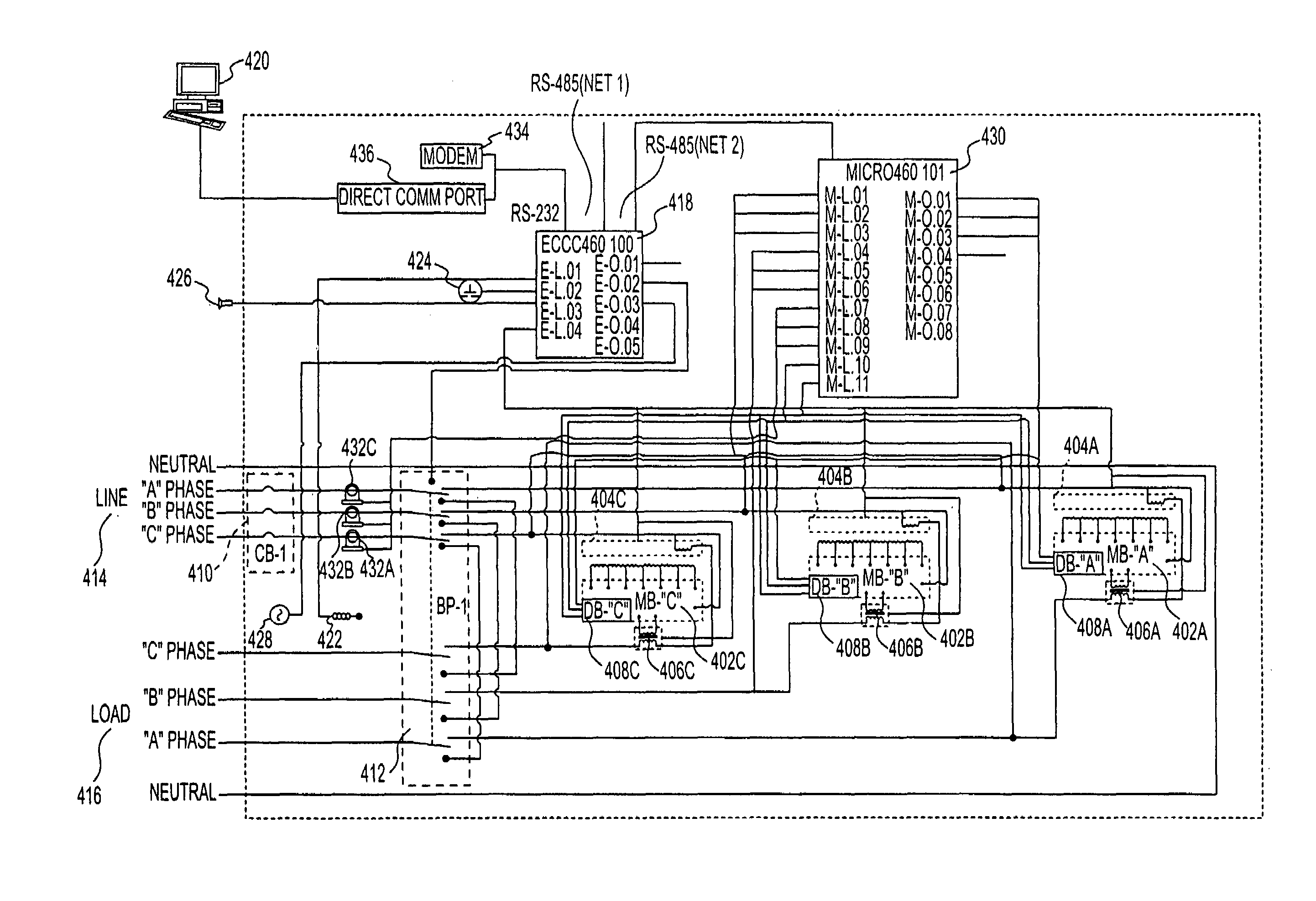
[0006]The processor controls the relays to provide an adjustable regulated voltage from each transformer winding. The energy reduction device thereby controls the output voltage on each phase to provide an individualized regulated voltage for each phase. The regulated voltage provided includes a sufficient voltage required to power the loads connected to that phase, plus an additional voltage which compensates for the voltage drop caused by the length of wire run in that phase. The electrical distribution system of the present invention eliminates the need for low voltage step-down transformers at the point of the load.
[0007]The energy reduction device can also regulate the voltage provided to lighting loads as a function of the time of day or the ambient light levels (as sensed by a light sensor near the lamps). A starting voltage can be applied to the lighting loads for a warmup period of predetermined length. The voltage supplied to the loads can also be reduced during periods of low public usage in order to save energy.

Problems solved by technology

One problem with this arrangement is that each lighting system is typically connected to the high voltage distribution transformer over a different length of wire ran.

Method used


Image

  • Electrical power distribution system for street lighting
  • Electrical power distribution system for street lighting
  • Electrical power distribution system for street lighting

Examples


Embodiment Construction

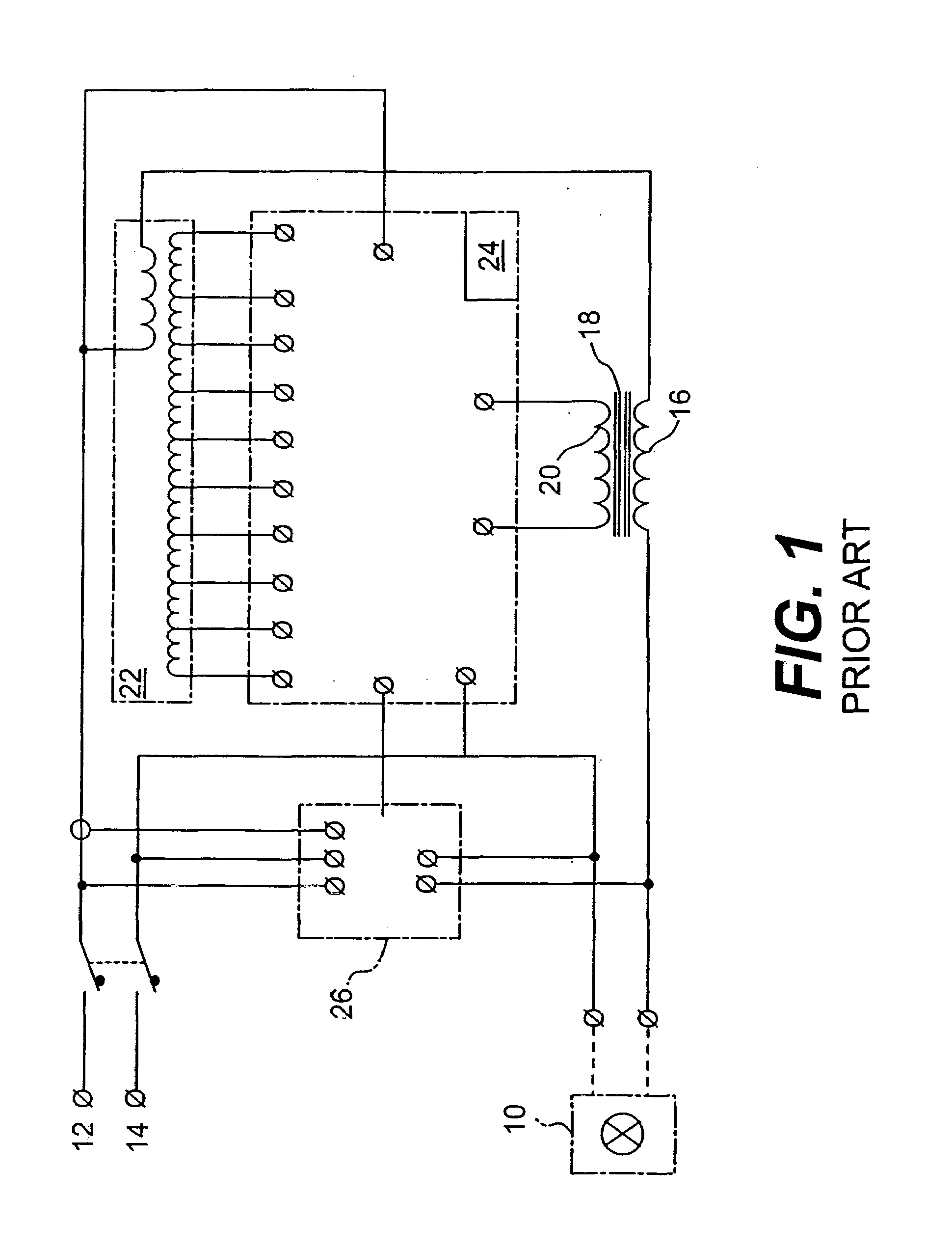
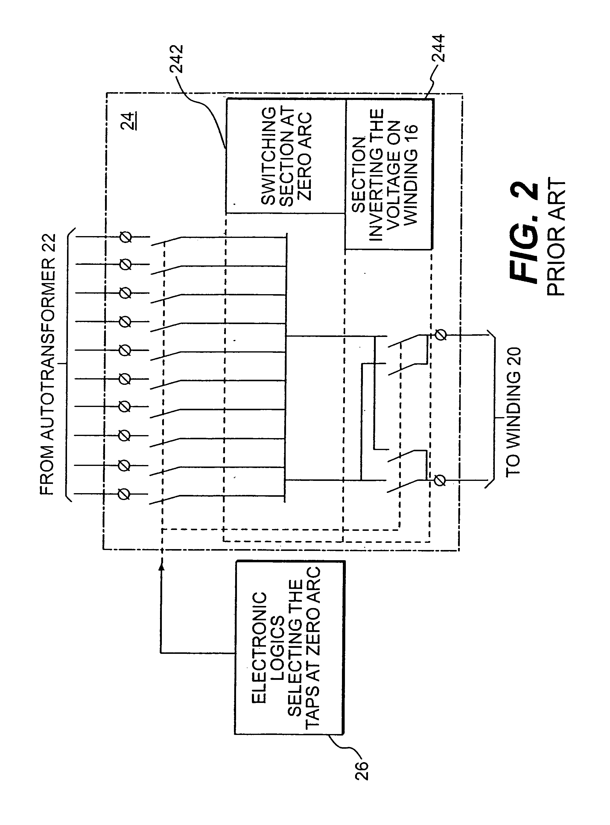
[0031]FIGS. 1–3 illustrate a power reducing device 100 which is described in PCT WO 98 / 53648. Power reducing device 100 is used in the system of the present invention, which will be described later beginning with FIG. 4.

[0032]Power reducing device 100 can work in a discrete manner, but is also able, by virtue of a precise calibration of the intervention steps, to progressively reduce or increase the power supplied to the lamps of a lighting application without abrupt voltage changes, both at the initial light-on, and at the final light-off time, while keeping a simple and reliable structure, therefor having an economical construction and servicing.

[0033]With reference to FIG. 1, a lighting system 100 is shown. A load 10 is modeled by a load lamp. Lighting system 100 is fed by monophasic alternating current taken between a phase 12 of a three-phase current circuit and the neutral phase 14 thereof.

[0034]In series with load 10 there is a winding 16, which impedance affects the voltage ...


PUM


Abstract

The invention comprises an electric power distribution system for providing power to a plurality of loads. An energy reduction device receives high voltage electrical power from a utility. A processor controls three variable transformer windings to produce electrical power at three phases at three independent reduced voltages. The energy reduction device thereby controls the output voltage on each phase to provide an individualized regulated voltage for each phase. The regulated voltage provided includes a sufficient voltage required to power the loads connected to that phase, plus an additional voltage which compensates for the voltage drop caused by the length of wire run in that phase. The electrical distribution system eliminates the need for low voltage step-down transformers at the point of the load. The energy reduction device can regulate the voltage provided to lighting loads as a function of the time of day or the ambient light levels.

Description

CROSS-REFERENCE TO RELATED APPLICATIONS[0001]This application is a continuation-in-part (CIP) of U.S. patent application Ser. No. 09 / 679,812 filed Oct. 5, 2000 (“Variable Base Load Energy Management System”) now U.S. Pat. No. 6,718,213, which claims the benefit of U.S. Provisional Application 60 / 212,622, filed Jun. 19, 2000.FIELD OF THE INVENTION[0002]The present invention relates to an electrical power distribution system for street lighting. More particularly, the present invention relates to a electrical power distribution system which independently regulates voltage for each of three phases as a function of ambient lighting, public usage, scheduling functions, and other parameters.BACKGROUND OF THE INVENTION[0003]In conventional electrical power distribution systems for distributing power to street lighting and other types of public lighting, several lighting systems are typically powered off of a central high voltage step-down distribution transformer. One problem with this arr...

Claims


Application Information

Patent Timeline
IPC IPC(8): G05F1/12G05B11/01G05D3/12
CPCG06Q50/06H05B37/0281Y02B20/40Y02B20/42Y02B20/72Y04S10/545Y02E40/76H05B47/16Y02E40/70Y04S10/50
Inventor ENBERG, DENIS
Owner STRATEGIC DESIGN FEDERATION W LLC
Learn More