
PC power monitoring

Inactive Publication Date: 2014-09-25
EMBERTEC
View PDF13 Cites 13 Cited by
  • Summary
  • Abstract
  • Description
  • Claims
  • Application Information

AI Technical Summary

Benefits of technology

The invention is an energy-saving device for computers that reduces energy usage by monitoring power use and supplying power to peripheral devices only when needed. The device has a low power standby mode that can be activated when the computing device is not actively being used. This results in a more efficient use of power in computer installations.

Problems solved by technology

However, users may find such entry to be inconvenient, especially when it is unexpected.
Since the delay period for entering standby is typically set by the user this often results in users setting extended time frames for the low power mode to be entered resulting in a significant delay before the onset of the power saving functionality.
Since a computer may be in use without such user input, this may lead to unexpected and unwanted activation of the low power mode.
Such an occurrence is likely to prompt a user to disable the low power mode or at least to extend the time period before it is entered.
The issue of unwanted entry into the standby mode is magnified when a user is working on the computer but not providing user input, such as when watching or giving a presentation such as a slide show or when involved in video conferencing.

Method used


Image

  • PC power monitoring
  • PC power monitoring
  • PC power monitoring

Examples


Embodiment Construction

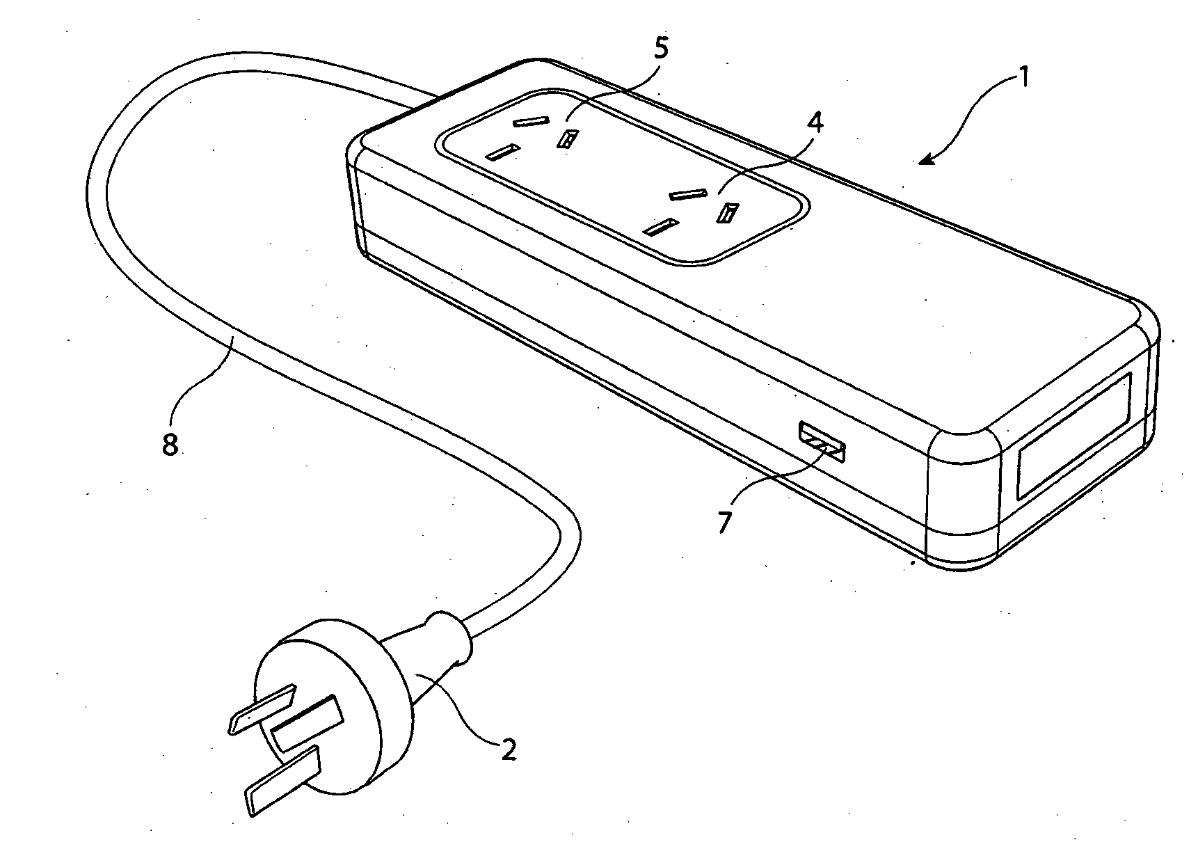
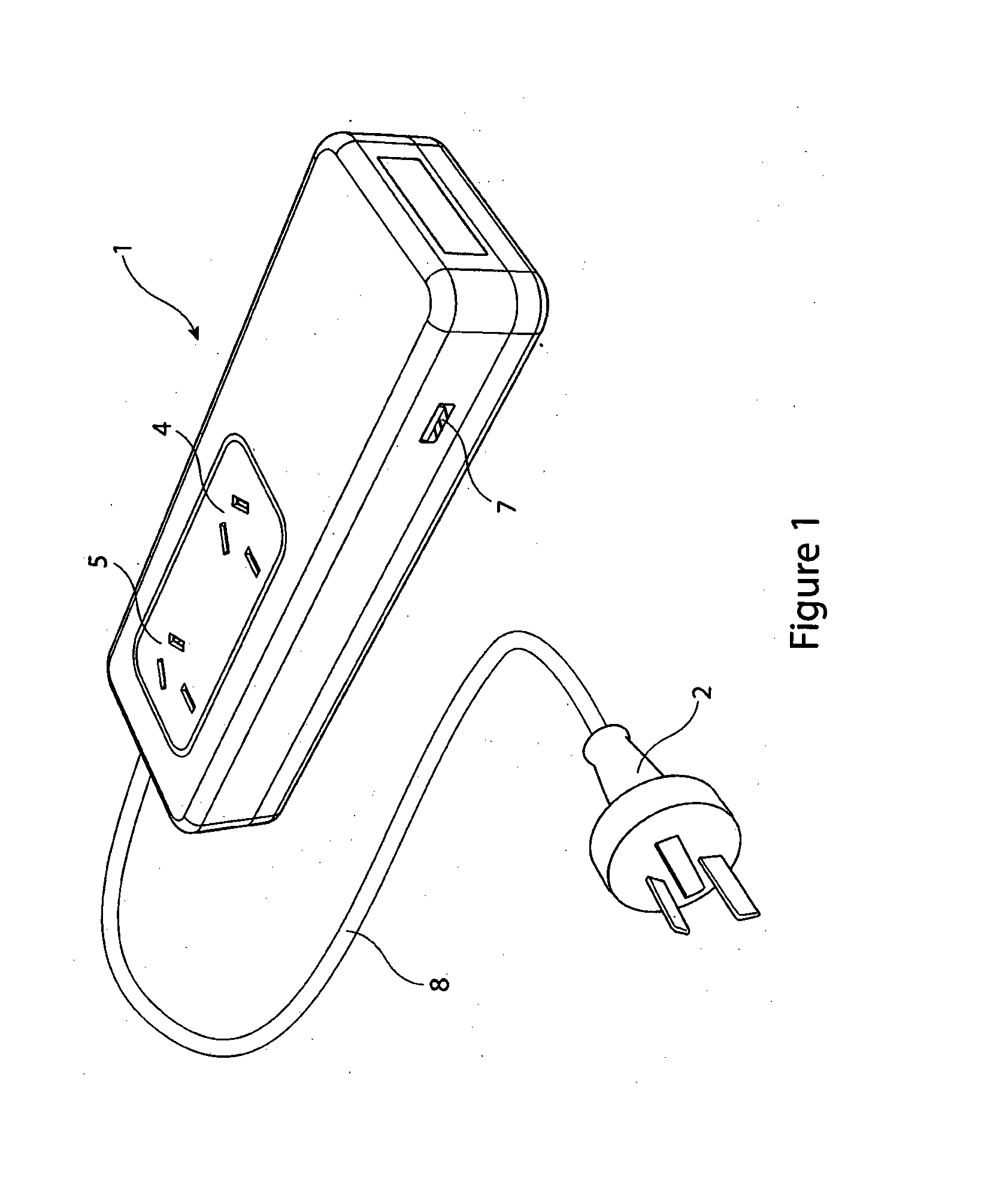
[0025]Referring now to FIG. 1, there is shown an energy saving device 1, which has a plug 2 which is adapted to be connected to a general purpose electrical outlet (GPO). The energy saving device 1 provides at least two electrical outlets 4,5 adapted to supply electrical power to electrical appliances. As illustrated there is a monitored electrical outlet 4 and a switched electrical outlet 5. In other embodiments multiples of either or both of these two types of outlet may be provided. Further outlets, which may be designated always on and which supply power at all times when power is provided to the energy saving device via plug 2 may also be provided.

[0026]Each electrical outlet of the energy saving device may be provided with identical electrical circuitry, with the function of the outlet being determined by software. Alternatively, each electrical outlet may include electrical circuitry specific to the function of that outlet.

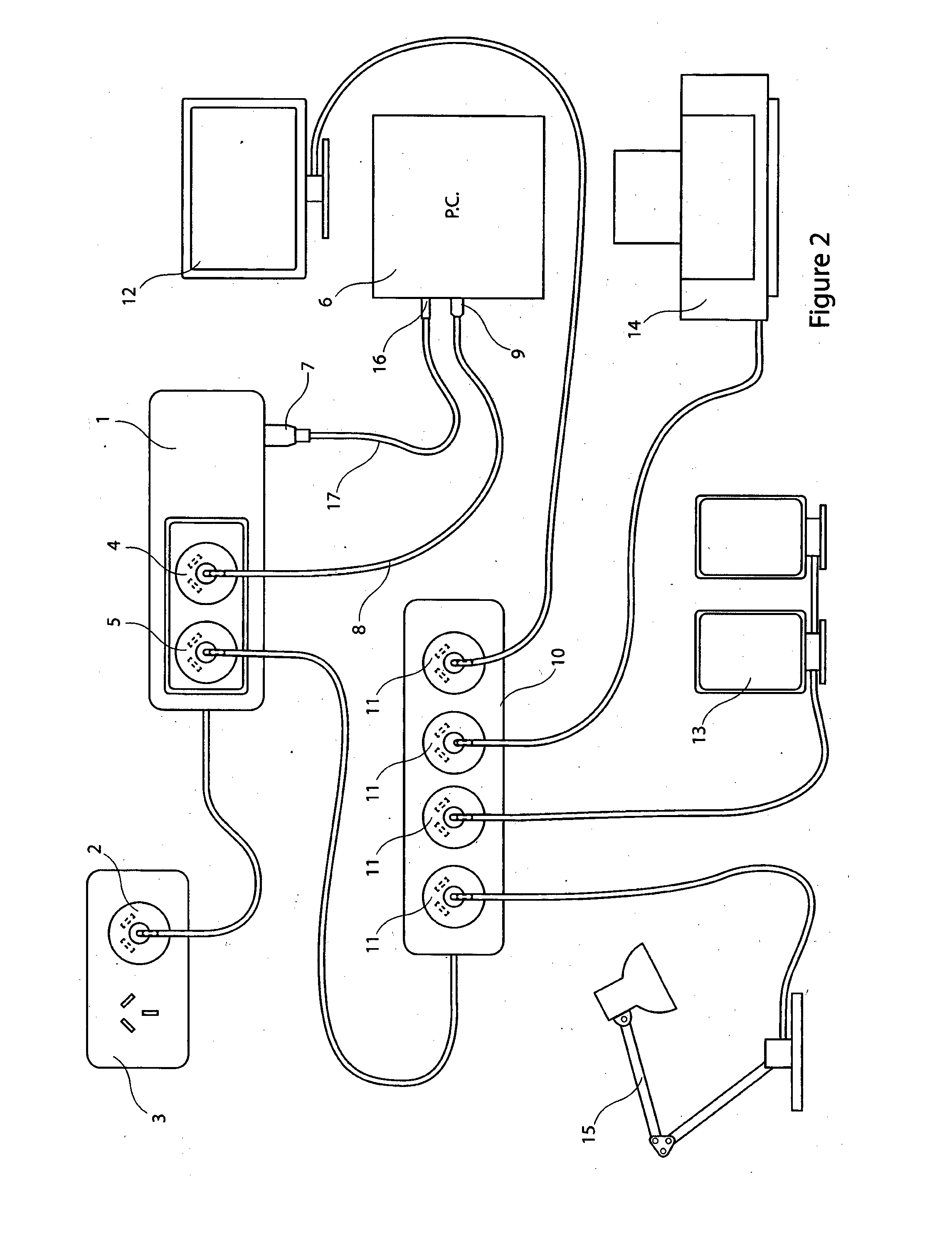
[0027]Referring now to FIG. 2, the energy saving devi...


PUM


Abstract

An energy saving device that has an electrical inlet which connects to a general power outlet, and has at least one monitored electrical outlet connecting to a computing device, the energy saving device having at least one switched electrical outlet which connects to, and supplies electrical power to, at least one peripheral device, which in a preferred embodiment is a computer monitor. The energy saving device includes a switch to control electrical connection of the inlet to the switched electrical outlet, and thus to control supply of electric power to the peripheral devices. Other peripherals may include printers, speakers and desk lamps.

Description

FIELD OF THE INVENTION[0001]The present invention relates to an apparatus and method to regulate the supply of power to and to control the power modes of a device, in particular of a computer.BACKGROUND[0002]Computer devices, in particular personal computer devices, enter a low power or standby mode when a user has not operated the computer for a defined period of time. This is sometimes referred to as a standby or low power mode.[0003]The low power or standby mode is often referred to as the “sleep” or “hibernate” mode, where the computer cuts or attempts to reduce the provision of power to superfluous areas of the computing device and allow a user to resume working or operating a machine from the standby mode without having to go through an extended reboot process.[0004]Entering a low power mode on a computer device will provide power savings. However, users may find such entry to be inconvenient, especially when it is unexpected. Since the delay period for entering standby is typ...

Claims


Application Information

Patent Timeline
IPC IPC(8): G06F1/32
CPCG06F1/3228G06F1/32Y02B60/1267G06F1/325G06F1/3206G06F1/3246H01R13/6683H01R13/70H01R25/003Y02B70/30Y04S20/20G06F1/3215G06F1/3231G06F2200/261H02J9/007Y02D10/00
Inventor GELONESE, GIUSEPPE ANTONIO
Owner EMBERTEC
Learn More