Recording apparatus

Inactive Publication Date: 2010-07-22
SEIKO EPSON CORP
View PDF4 Cites 14 Cited by
  • Summary
  • Abstract
  • Description
  • Claims
  • Application Information

AI Technical Summary

Benefits of technology

[0016]According to the fourth embodiment of the invention, since the exterior air introduced into the drying unit is heated using heat tran

Problems solved by technology

However, since in the drying unit disclosed in JP-B-7-121580, heated air flows in parallel to the ink attached surface of the medium, the efficiency of heat transfer to the medium decreases and the heated air needs to be blown over a wide range in order to sufficiently promote the drying operation, making the size of the drying unit larg

Method used


Image

  • Recording apparatus
  • Recording apparatus
  • Recording apparatus

Examples


Example

First Embodiment

[0026]Hereinafter, the first embodiment of the invention will be described with reference to FIGS. 1 and 2.

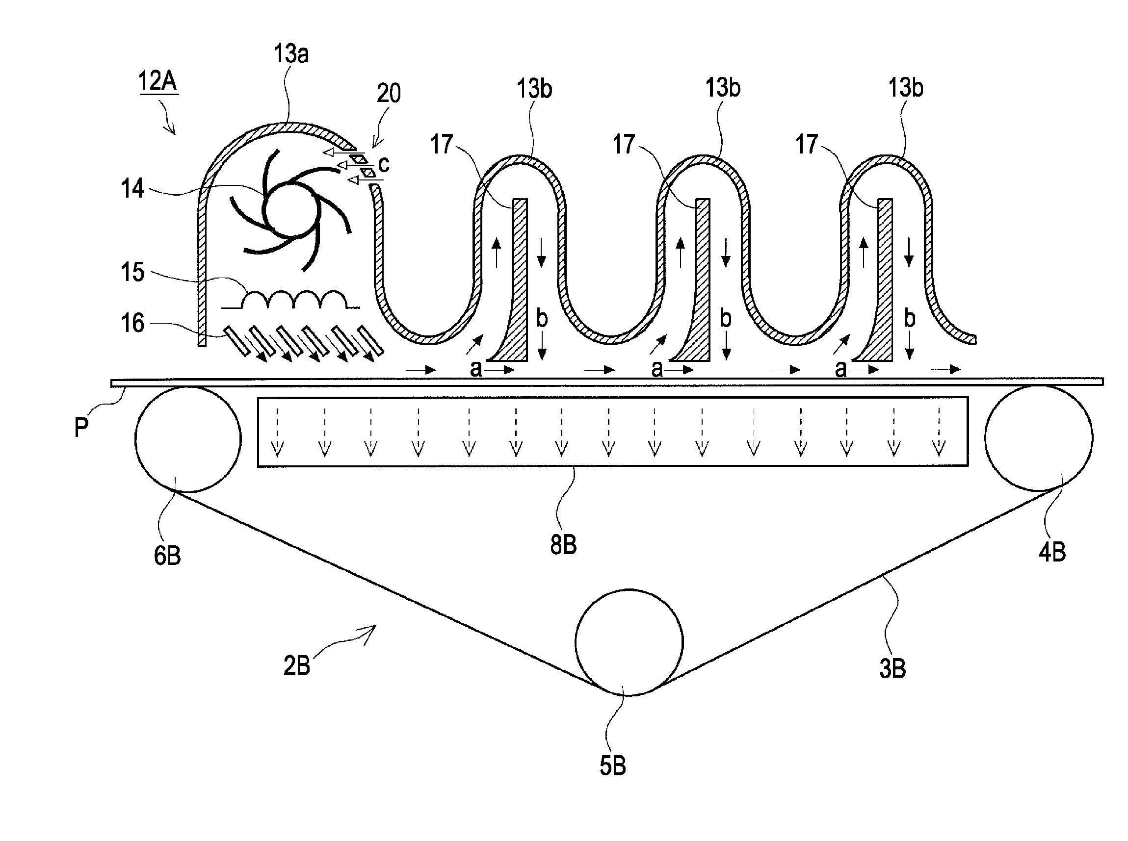
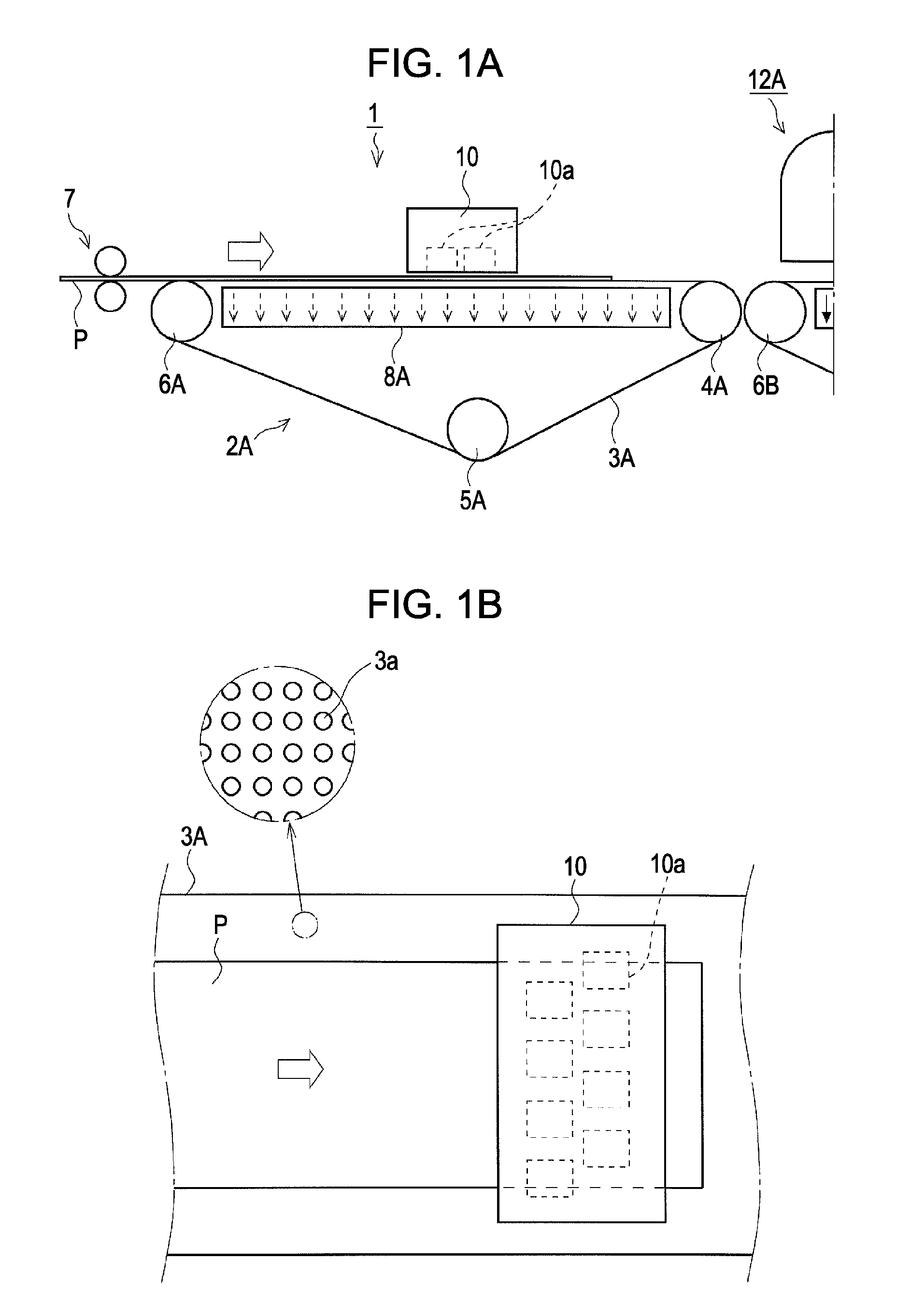
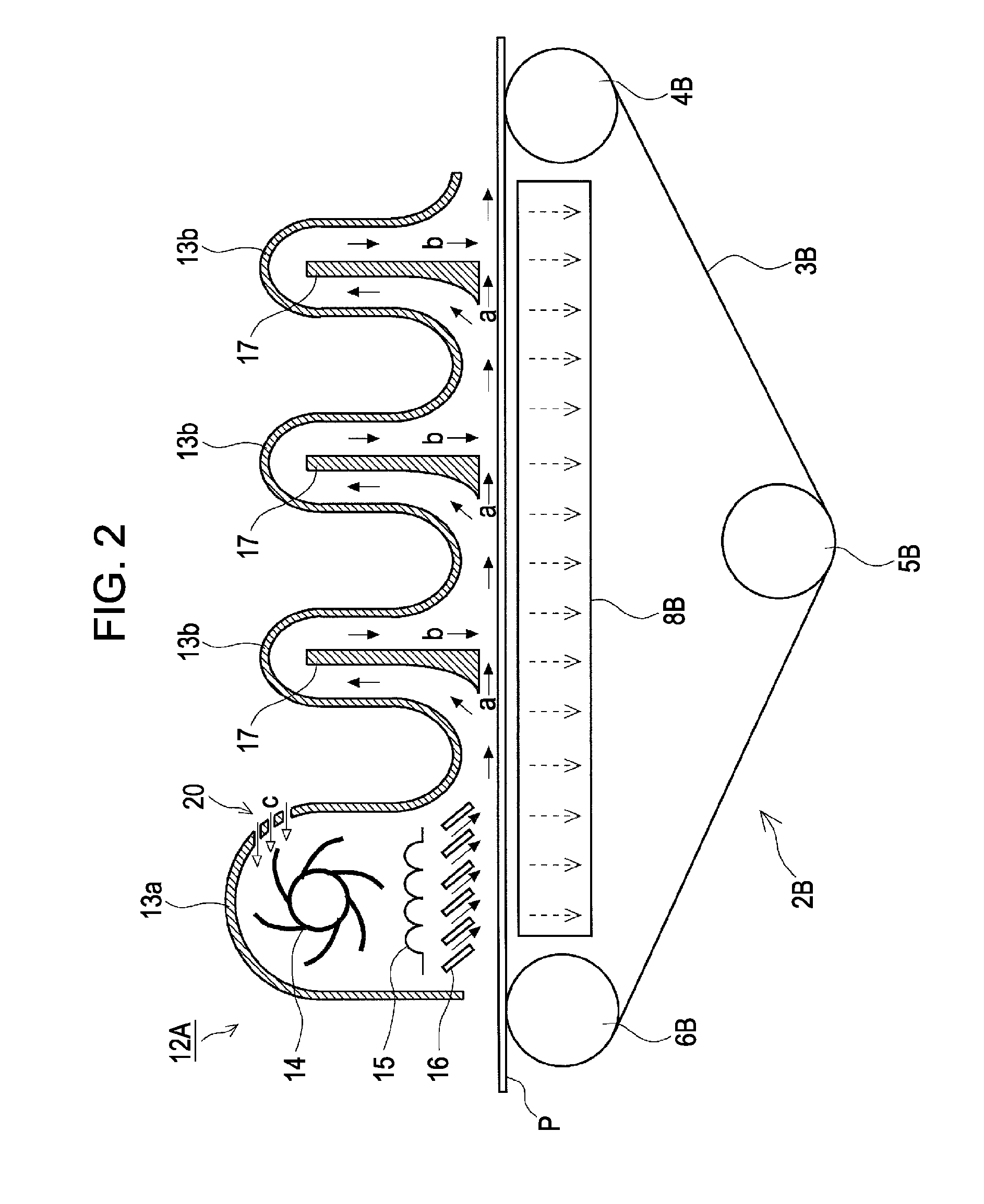
[0027]The printer 1 according to the embodiment of the invention is a high through-put ink jet printer of a line head type that includes an ink jet type recording head (recording unit) 10 having a length covering the width of a paper sheet and performs a recording operation by ejecting ink from a recording head 10 while moving the recording paper sheet P as an example of the recording medium in the paper sheet transport direction without reciprocating the ink ejection head in the widthwise direction of the paper sheet.

[0028]In more detail, the printer 1 has gate rollers 7 on the upstream side of the transport unit 2, and the recording paper sheet P is supplied to the transport unit 2 on a downstream side (the right direction in FIG. 1B) by the gate roller 7, after skew is removed before the recording paper sheet P is supplied to the transport unit 2.

[0029]A tran...

Example

Second Embodiment

[0040]Hereinafter, the second embodiment of the invention will be described with reference to FIG. 3. In the following embodiments including the second embodiment of the invention, the same elements as the first embodiment of the invention are endowed with the same reference numerals with reference to FIGS. 1 and 2 for which reason a detailed description thereof will be omitted.

[0041]The drying unit 12B according to the second embodiment of the invention includes auxiliary fans 22 above the blades 17. The flow rate of the sub-passage b is improved by the auxiliary fans 22 when the sub-passage b merges with the main passage a, increasing the efficiency of heat transfer to the recording paper P, whereby drying of the ink is promoted and a remarkable pressing effect (floating prevention effect) of the recording paper sheet P can be obtained.

Example

Third Embodiment

[0042]Hereinafter, the third embodiment of the invention will be described with reference to FIG. 4. The drying unit 12C according to the third embodiment of the invention includes a cover 19 above the sub-case 13b, and a serpentine space (serpentine passage) is formed between the sub-case 13b and the cover 19.

[0043]The serpentine passage is an exterior air intake passage into the main case 13a, and the exterior air (indicated by white arrows) introduced from the exterior air intake port 21 is heated to be the exterior air c′ by the heat transfer from the sub-case 13b and is guided into the main case 13a. Therefore, according to the embodiment of the invention, energy (of the heater 15) can be saved by efficiently using the heat of the sub-passage b.

[0044]The reference numeral 18 indicates auxiliary heaters and the drying efficiency of the ink can be additionally enhanced by raising the temperature of the sub-passage b or preventing the lowering of the temperature of...


PUM


Abstract

A recording apparatus includes: a recording unit that performs a recording operation on a recording medium; a transport unit that transports the recording medium; and a drying unit that promotes drying of the recording medium by ejecting gas to the recording medium. The drying unit includes a main passage through which the gas flows on a surface of the recording medium along the transport direction of the recording medium, and a sub-passage that merges with the main passage and extends in a direction crossing the surface of the recording medium when merging with the main passage.

Description

BACKGROUND[0001]1. Technical Field[0002]The present invention relates to a recording apparatus such as a facsimile machine, a printer, etc., and more particularly to a recording apparatus including a drying unit that promotes a drying operation of a recording medium.[0003]2. Related Art[0004]As disclosed in JP-B-7-121580, dryers for drying ink on printed mediums have been conventionally suggested. In the drying unit described in JP-B-7-121580, heated air flows in parallel to an ink attached surface of the medium when the medium to which ink is attached proceeds along a medium path and then is guided to a heating element again to be re-circulated.[0005]Meanwhile, JP-A-2002-292841 discloses a printer including a drying unit that dries ink attached to a paper sheet by ejecting hot air almost perpendicular to the paper sheet.[0006]However, since in the drying unit disclosed in JP-B-7-121580, heated air flows in parallel to the ink attached surface of the medium, the efficiency of heat t...

Claims


Application Information

Patent Timeline
IPC IPC(8): B41F23/00
CPCB41J11/002B41J11/0085B41J11/007B41J11/0022
Inventor SHIOHARA, SATORU
Owner SEIKO EPSON CORP
Why Eureka
Try Eureka