Surveying instrument and surveying operation system
Active Publication Date: 2015-02-26
KK TOPCON
View PDF12 Cites 13 Cited by
Summary
Abstract
Description
Claims
Application Information
AI Technical Summary
This helps you quickly interpret patents by identifying the three key elements:
Problems solved by technology
Method used
Benefits of technology
Benefits of technology
The present invention provides a surveying instrument that saves energy and maintains surveying operation efficiency by automatically tuning off guide light when a target is locked. This prevents deterioration in surveying operation efficiency that might occur when the target light is turned off.
Problems solved by technology
However, the surveying operation system with such a surveying instrument has an energy saving problem because the pedestal rotates while irradiating with the guide light.
However, when the irradiation of the guide light is stopped in the case of locking the target, the surveying operation efficiency by an operator may be deteriorated because target light is turned off if the locking of target is released for some reason after the target is locked.
Method used
Image
Click on the blue label to locate the original text in one second.
Reading with bidirectional positioning of images and text.
Examples
embodiment
[0027]Hereinafter, an embodiment of a surveying instrument according to the present invention will be described with reference to the drawings.
(Configuration of Surveying Instrument)
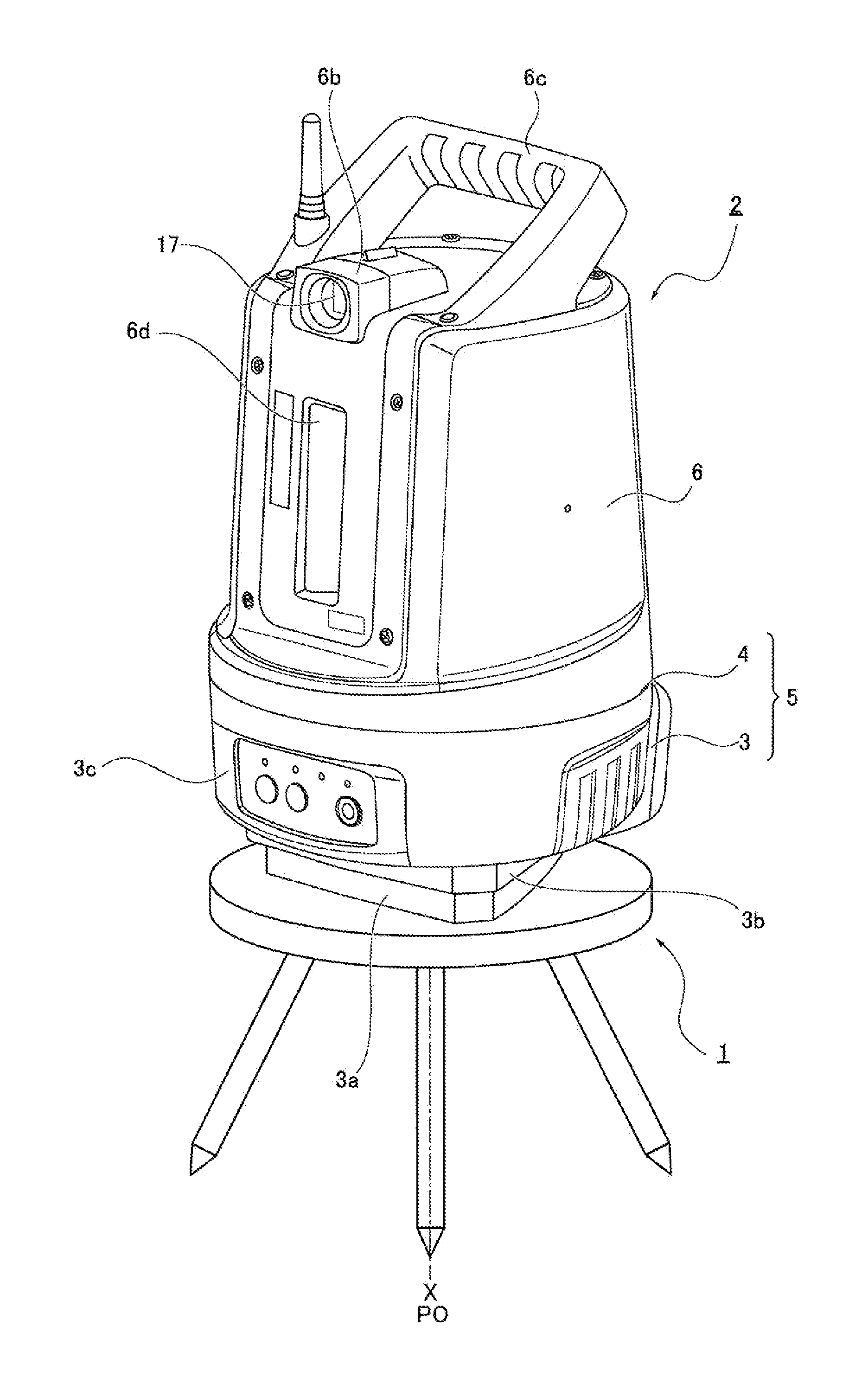
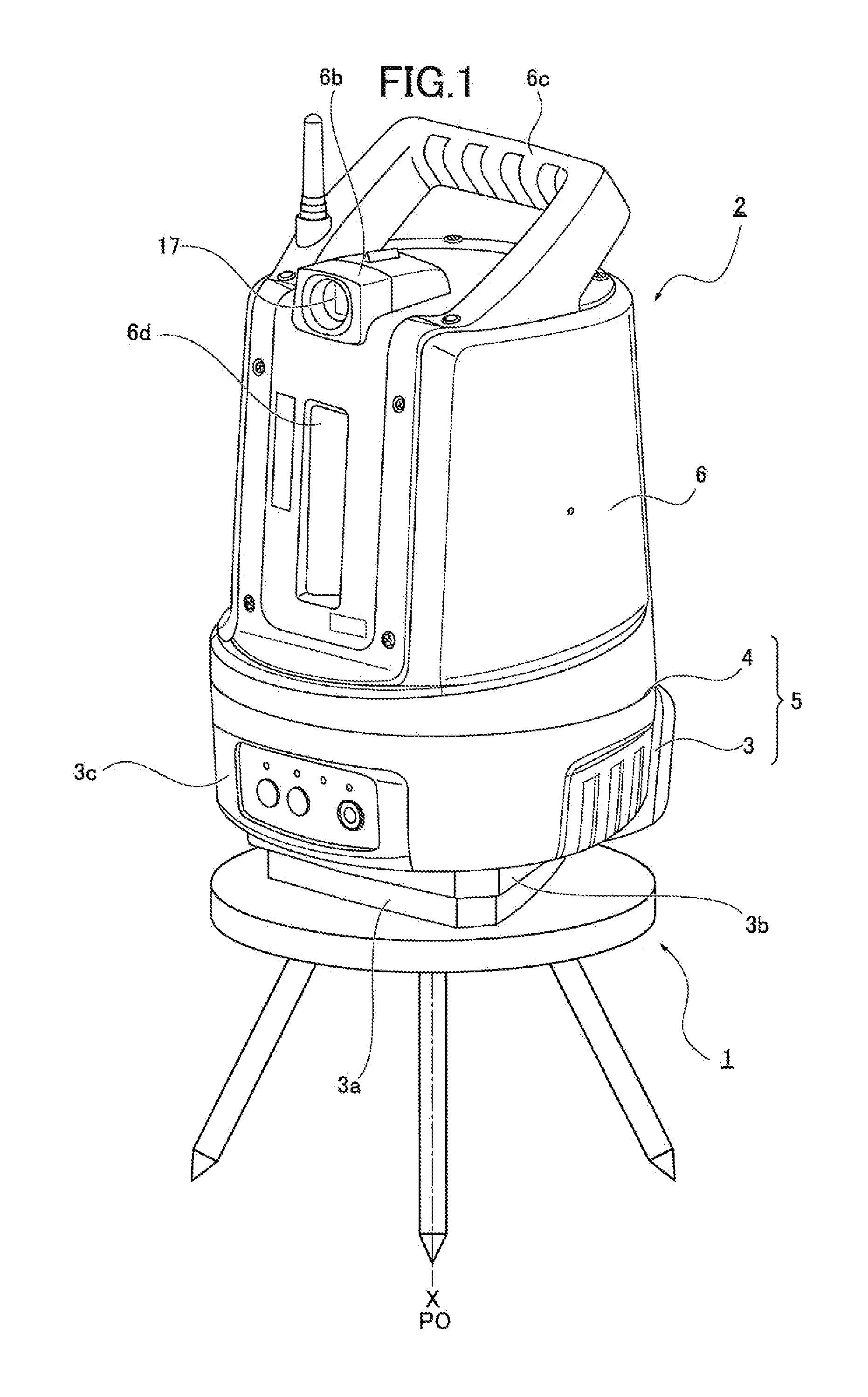
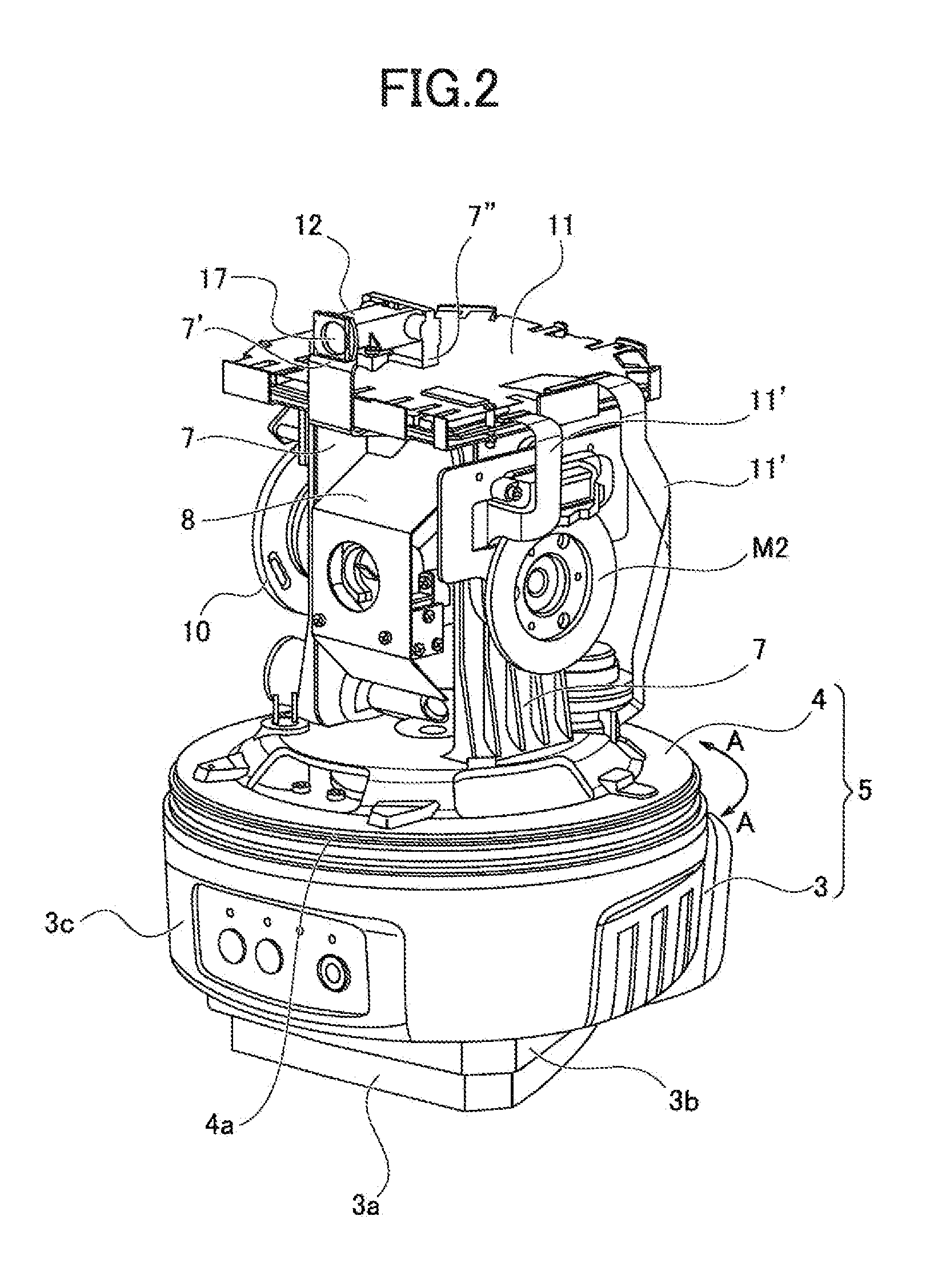
[0028]Referring to FIG. 1, reference number 1 denotes a tripod and reference number 2 denotes a surveying instrument. The surveying instrument 2 includes a main body 5 having a base 3 and a pedestal 4 rotating in a horizontal direction relative to the base 3 as illustrated in FIG. 2, and a cover member 6, as illustrated in FIG. 1.
[0029]The base 3 includes a seat 3a fixed to the tripod 1, a leveling base 3b having a not-shown leveling screw, and a case 3c having inside thereof a driving mechanism such as a horizontal direction-driving motor M1 (refer to FIG. 4) which rotates and drives the pedestal 4 in a horizontal direction (arrow A direction, as illustrated in FIG. 2).
[0030]The pedestal 4 is provided with a support member 7, as illustrated in FIGS. 2, 3. The support member 7 is provided with a horizont...
modified example
[0083]FIGS. 11A, 11B are views illustrating a modified example of the guide light irradiation unit 12. In this modified example, the guide light irradiation unit 12 includes a light-emitting diode LED G which generates green light PG and a light-emitting diode LED R which generates red light PR, as illustrated in FIG. 11A.
[0084]Aperture stop members 40a, 40b are provided just in front of the light-emitting diode LED G and the light-emitting diode LED R, respectively. Each of the aperture stop members 40a, 40b is configured to cut half of each light.
[0086]The green light PG and the red light RG are emitted from the guide light irradiation unit 12 as the fan-like guide light PB2.
[0087]In addition, in this embodiment, the objective lens 30 of the tracking optical system 14 and the objective lens 19 of the ranging optical system 13 are separated. However, the objectiv...
PUM
Abstract
A surveying instrument includes a pedestal provided with a guide light irradiation unit provided with a light source to irradiate with guide light indicating a collimation direction of the surveying instrument to an operator, a tracking optical system which locks a target, a ranging optical system which ranges a distance to the target, and a control circuit which calculates surveying data by a ranging result of the ranging optical system, and a transmitting and receiving unit which receives survey setting point data regarding a survey setting operation and sends the surveying data obtained by the control circuit.
Description
PRIORITY CLAIM[0001]The present application is based on and claims priority from Japanese Patent Application No. 2013-173522, filed on Aug. 23, 2013, the disclosure of which is hereby incorporated by reference in its entirety.BACKGROUND[0002]1. Field of the Invention[0003]The present invention relates to a surveying instrument including a guide light optical system which irradiates with guide light and a surveying operation system.[0004]2. Description of the Related Art[0005]A surveying instrument provided with a guide light irradiation unit which irradiates with guide light indicating a collimation direction of a surveying instrument to an operator is conventionally known (refer to, for example, JP2012-202821A).[0006]Such a surveying instrument includes a base and a pedestal rotating in a horizontal direction relative to the base. The pedestal is provided with a support member. The support member supports a lens barrel of a ranging optical system to be rotatable in a vertical direc...
Claims
Application Information
Patent Timeline
Application Date:The date an application was filed.
Publication Date:The date a patent or application was officially published.
First Publication Date:The earliest publication date of a patent with the same application number.
Issue Date:Publication date of the patent grant document.
PCT Entry Date:The Entry date of PCT National Phase.
Estimated Expiry Date:The statutory expiry date of a patent right according to the Patent Law, and it is the longest term of protection that the patent right can achieve without the termination of the patent right due to other reasons(Term extension factor has been taken into account ).
Invalid Date:Actual expiry date is based on effective date or publication date of legal transaction data of invalid patent.

