Chain assembling-disassembling structure

Inactive Publication Date: 2011-07-28
HO CHI ENTERPRISES
View PDF6 Cites 20 Cited by
  • Summary
  • Abstract
  • Description
  • Claims
  • Application Information

AI Technical Summary

Benefits of technology

[0005]The object of the present invention is to provide a chain assembling-disassembling structure which can rapidly disassemble the chain by removing the pin for jointing the inner and outer link plates, and can re-assemble two adjacent chain sections after changing the length

Problems solved by technology

However, when the chain is used in different applications, it always needs to change the number of link plates for varying the length of the chain.
Conventionally, when disassembling the pin 3, an acicular object is a

Method used


Image

  • Chain assembling-disassembling structure
  • Chain assembling-disassembling structure
  • Chain assembling-disassembling structure

Examples


Example

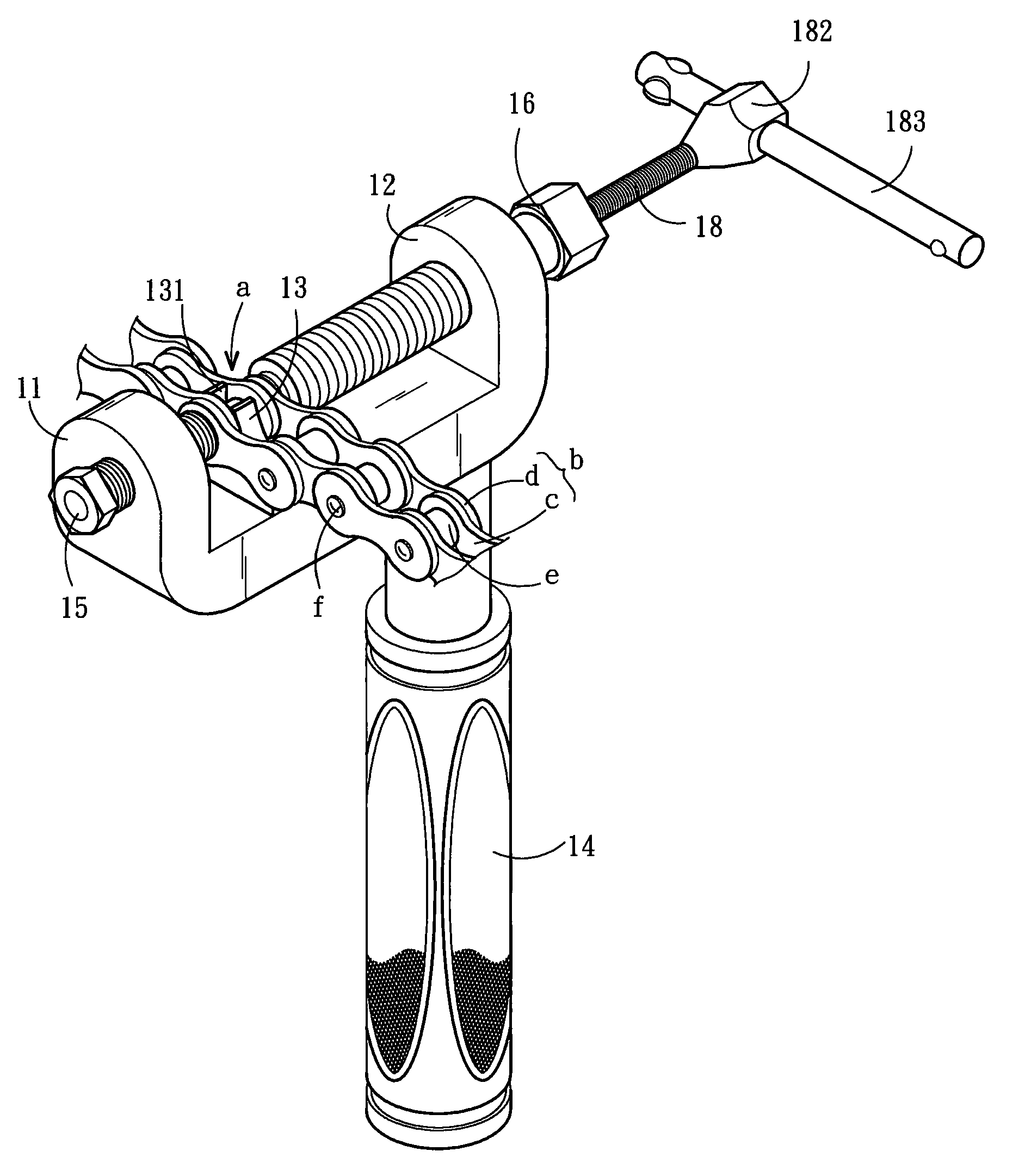
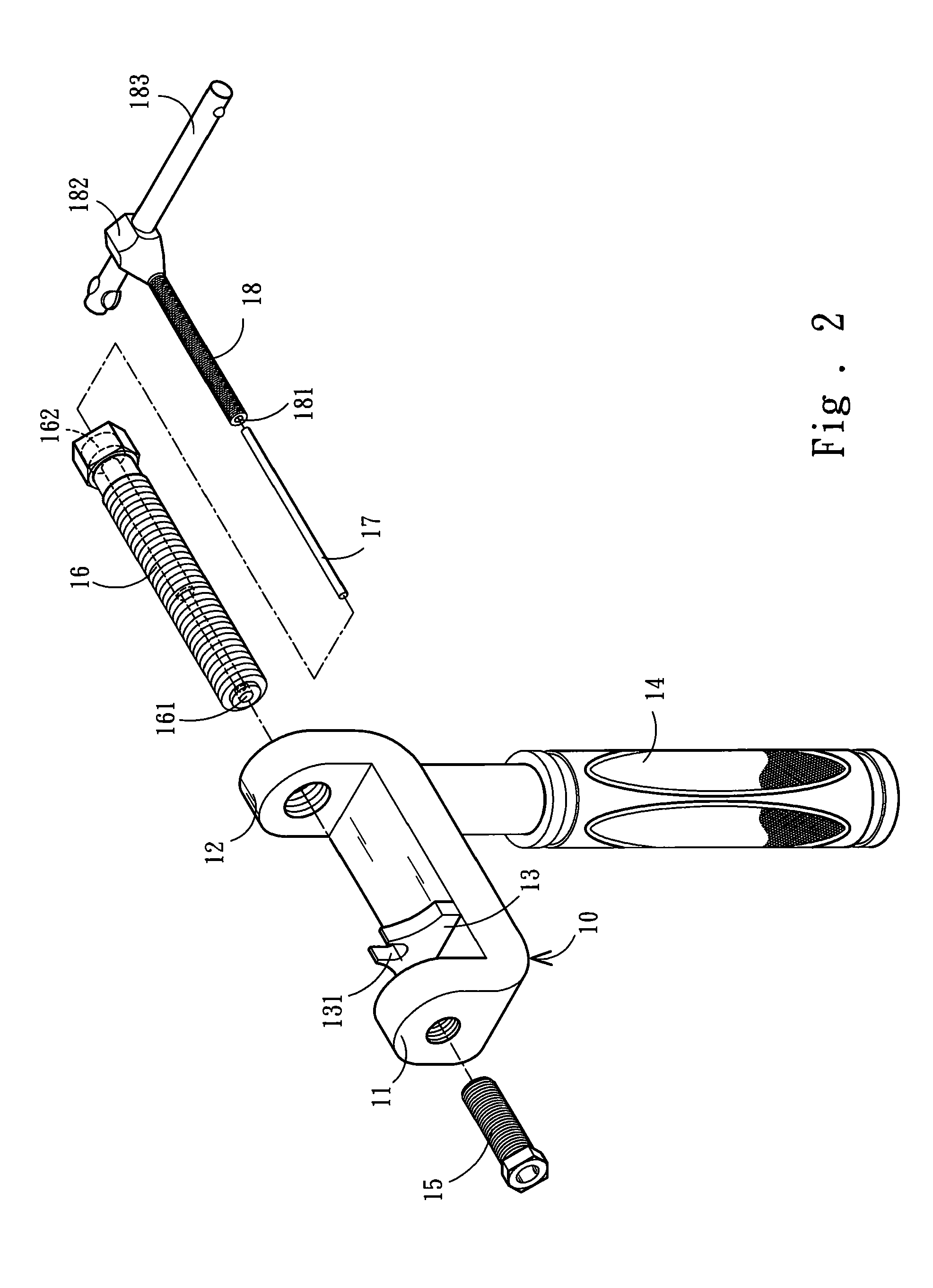
[0024]Please refer to FIG. 2, FIG. 3 and FIG. 5A. The present invention provides a chain assembling-disassembling structure for disassembling a chain section b of a chain a. The chain section b is composed of a pair of inner link plates c and a pair of outer link plates d. Two bushings e are mounted between the inner link plates c, and a pin f penetrates through the inner link plates c, the outer link plates d and the bushing e for jointing the inner link plates c with the outer link plates d. The chain assembling-disassembling structure includes an assembling base 10, a first clamping component 15, a second clamping component 16, a penetrating shaft 17 and a driving shaft 18.

[0025]The assembling base 10 has a horizontal bottom surface with a first portion 11 and a second portion 12 vertically formed at two opposite ends thereof. At the middle of the assembling base 10, a fixing portion 13 of a slice shape is mounted. The fixing portion 13 has a concave edge 131 at the top thereof c...


PUM

PropertyMeasurementUnit
Structureaaaaaaaaaa

Abstract

A chain assembling-disassembling structure includes an assembling base, a first clamping component, a second clamping component, a penetrating shaft and a driving shaft. The assembling base has a fixing portion and the fixing portion has a concave edge for receiving a bushing of the chain section. And, the assembling base includes a first portion and a second portion vertically formed at two opposite ends thereof for respectively engaging with the first and second clamping components. Here, the first and second clamping components together clamp and restrict the chain. The second clamping component has a tubular shape for being inserted by the penetrating shaft, and then, the driving shaft can further be locked into the second clamping component. By turning the driving shaft, the penetrating shaft can be forced to push out a pin, which is used for jointing the inner and outer link plates of the chain.

Description

FIELD OF THE INVENTION[0001]The present invention is related to a tool for assembling-disassembling a chain section of a chain, and more particularly to a tool for conveniently and rapidly assembling-disassembling a pin in the chain section.BACKGROUND OF THE INVENTION[0002]As shown in FIG. 1, the general chain includes plural inner link plates 1 and outer link plates 2 which are corresponding to each other. The outer link plates 2 are attached to the outer surfaces of the inner link plates 1, and a pin 3 penetrates through a bushing 4 between two outer link plates 2 and two inner link plates 1 with two ends exposed out of the outer sides of the two outer link plates 2. Here, one end of the pin 3 has a bolt head 5, and the other end also should be riveted after passing through two inner link plates 1, two outer link plates 2 and the bushing 4, so as to joint the inner and the outer link plates 1, 2 together.[0003]However, when the chain is used in different applications, it always ne...

Claims


Application Information

Patent Timeline
IPC IPC(8): B21L9/06
CPCB21L9/065Y10T29/5377B21L21/00
Inventor YU, MIN-CHI
Owner HO CHI ENTERPRISES
Why Eureka
Try Eureka