Apparatus for the simultaenous filling of precise amounts of viscous liquid material in a sanitary environment

Inactive Publication Date: 2005-08-11
COTT TECH
View PDF4 Cites 21 Cited by
  • Summary
  • Abstract
  • Description
  • Claims
  • Application Information

AI Technical Summary

Benefits of technology

[0018] Accordingly, the sanitary filling apparatus in accordance with the invention is advantageous in being adaptable to quickly and efficiently deliver a variety of viscous liquid materials in a sanitary fashion. For instance, the combination of the sanitary pump, pulsation dampener and fill valve permits simultaneous filling operations of a plurality of containers with precise amounts of viscous liquid material regardless of whether the container is upstream or downstream of the manifold, and regardless of temperature or humidity of the outside environment in which the sanitary filling apparatus is located.
[0019] The sanitary pump is simplistic in design, utilizes interchangeable parts, and has rapid disassembly of the components to provide for clean-in-place (CIP) advantages required for dispensing viscous liquid material in the food processing and pharmaceutical industry. These same CIP and disassembly advantages permit the sanitary pump to be disassembled and transported easily to remote locations to establish pumping operations in either sanitary or non-sanitary environments or applications where reliability, high pressure, high flow and particularly a constant pressure pump is desired. Moreover, the sanitary pump of the invention utilizes high-speed, sanitary and interchangeable check valves which permit the pump to operate at speeds up to and exceeding 200 cycles per minute utilizing a positively controlled drive shaft.
[0020] The pulsation dampener provides additional a

Problems solved by technology

Heretofore, pump delivery systems that pump viscous liquid materials to various sources in precise and accurate flow rates are difficult to achieve due to the pulsing, surging, or hydraulic shock generated by the output of the pump mechanism.
Such pulsing, surging or otherwise hydraulic shock is undesirable since it typically results in hydraulic hammer in process lines, large pressure fluctuations, excessive wear and increased cost of maintenance of pumps and instruments, inaccurate flow rates during delivery operations, which results in increased material costs and time.
Moreo

Method used


Image

  • Apparatus for the simultaenous filling of precise amounts of viscous liquid material in a sanitary environment
  • Apparatus for the simultaenous filling of precise amounts of viscous liquid material in a sanitary environment
  • Apparatus for the simultaenous filling of precise amounts of viscous liquid material in a sanitary environment

Examples


Example

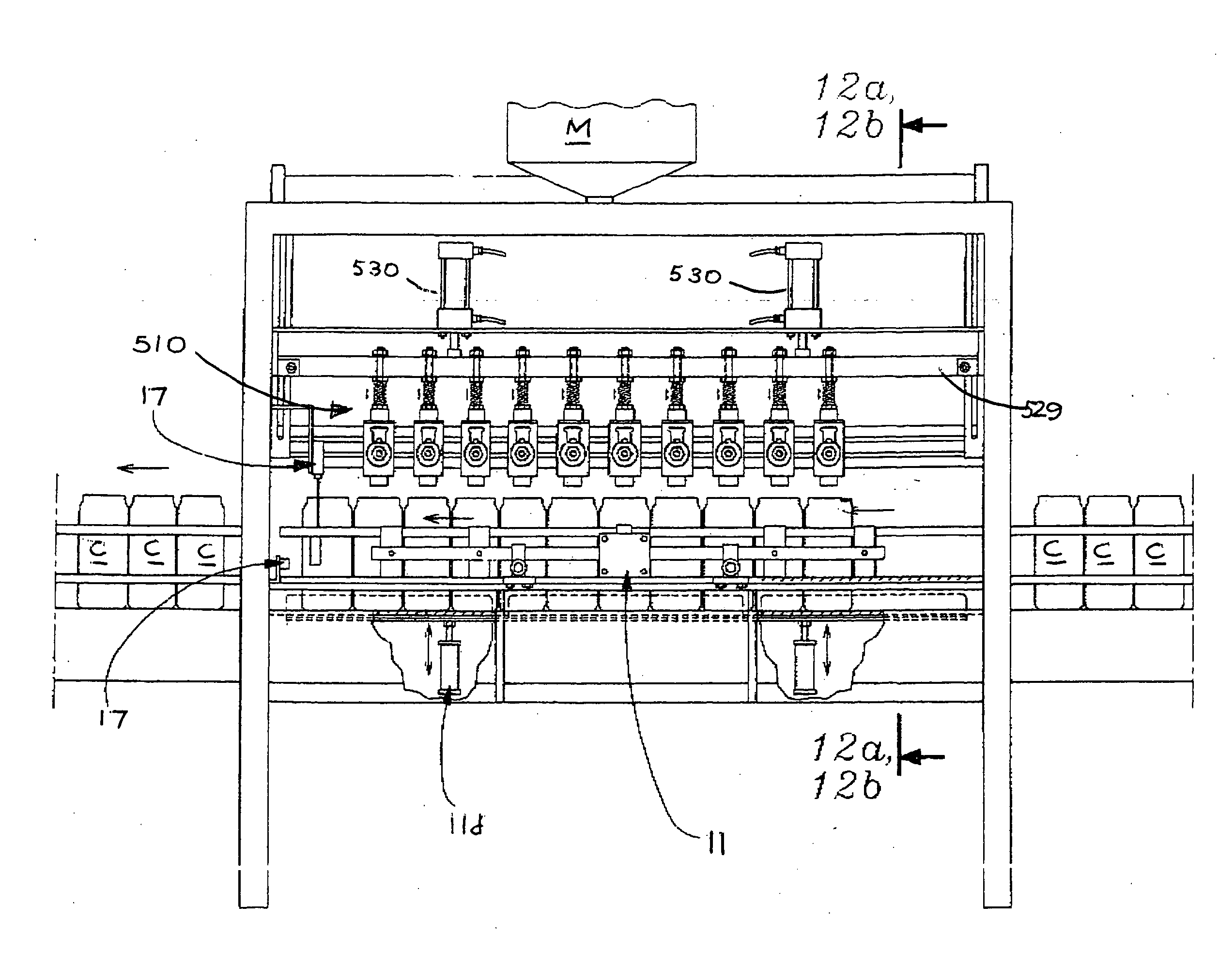
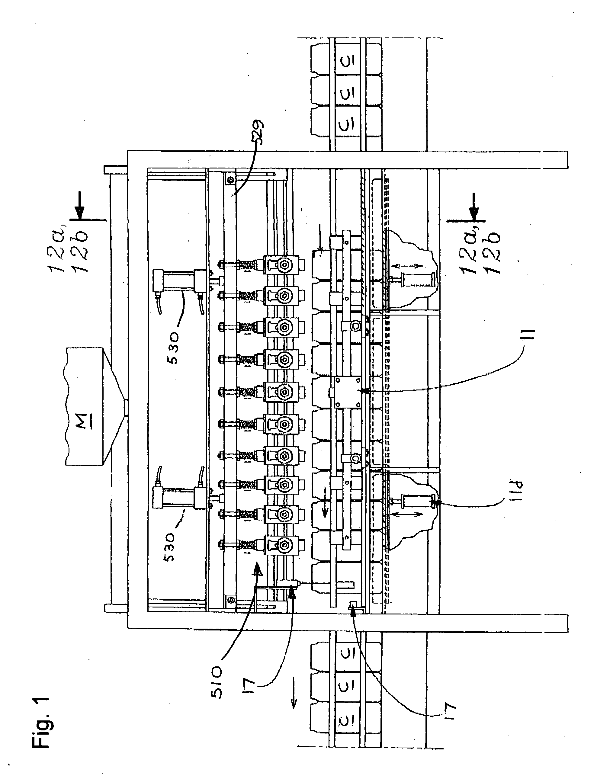
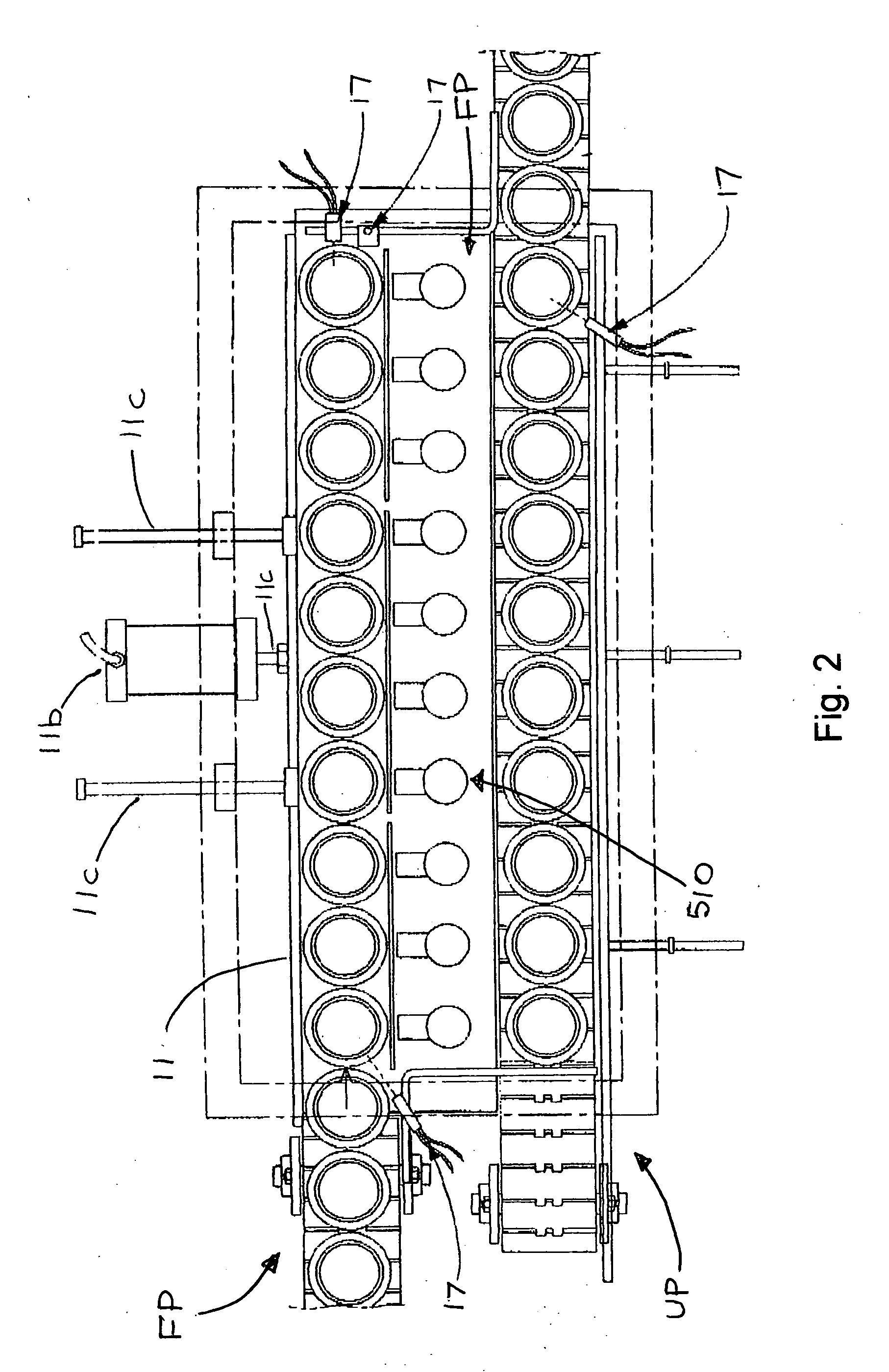
[0053] As shown in FIGS. 1-29, the sanitary filling apparatus includes the combination of a sanitary pump mechanism 10 for delivering viscous liquid material L nder pressure in precise amounts to a viscous liquid material manifold M, a pump pulsation dampening assembly 350 provided in series between the sanitary pump mechanism 10 and the viscous liquid material manifold M for substantially reducing the pulsating fluid flow of the viscous liquid material, and a plurality of sanitary fill valves 510 arranged sequentially and coaxially above a plurality of containers C for drawing the viscous liquid material L from the viscous liquid material manifold M and simultaneously filling or otherwise dispensing a precise metered amount of the viscous liquid material L into the containers C. The fill valves 510 are removably attached to a horizontally disposed press bar 529, the fill valve 510 having at least one pair of pneumatic valve actuator cylinders 530 for displacing a respective valve p...


PUM

PropertyMeasurementUnit
Lengthaaaaaaaaaa
Pressureaaaaaaaaaa
Flow rateaaaaaaaaaa

Abstract

An automated apparatus for the simultaneous filling of precise quantities of viscous liquid material to a plurality of containers in a sanitary environment, including a sanitary pump for delivering under pressure the viscous liquid material to a viscous liquid material manifold, a pump pulsation dampening assembly for dampening any pulsating output produced by the sanitary pump, and a plurality of fill valves for simultaneously dispensing a precise amount of viscous liquid material to the containers during a filling operation.

Description

BACKGROUND OF THE INVENTION [0001] 1. Field of the Invention [0002] This invention relates generally to an automated apparatus for the high-speed delivery of precisely measurable quantities of a variety of viscous liquid materials having varying characteristics to a plurality of containers in a sanitary environment. [0003] 2. Description of the Related Art [0004] A wide variety of sanitary filling operations, especially in the pharmaceutical and food processing industries require high-speed fluid metering systems capable of delivering precisely measured quantities of viscous liquid materials at accurate flow rates to various locations and in a sanitary manner. Typical filling operations involve a delivery apparatus for delivering viscous liquid material to a viscous liquid material manifold, and a plurality of fill heads adapted to simultaneously dispense the viscous liquid material into a batch or plurality of empty vessels (i.e., bottles, containers or the like) to a plurality of ...

Claims


Application Information

Patent Timeline
IPC IPC(8): B65B3/04B65B3/12B65B3/30F04B5/02
CPCB65B3/12F04B5/02B65B3/30
Inventor NAVARRO, RAMON M.
Owner COTT TECH
Why Eureka
Try Eureka