Linear motor

a linear motor and motor shaft technology, applied in the field of linear motors, can solve problems such as cogging thrust, and achieve the effect of decreasing cogging thrus

Inactive Publication Date: 2011-09-15
YASKAWA DENKI KK
View PDF5 Cites 12 Cited by
  • Summary
  • Abstract
  • Description
  • Claims
  • Application Information

AI Technical Summary

Benefits of technology

[0010]In the aspect of the present invention, a plurality of permanent magnets is linearly arranged on a field yoke so that the polarities thereof are alternated, thereby constituting a field system. The armature is disposed facing the field system with a magnetic air gap therebetween, and the armature winding is wound around the main teeth provided in the armature core. Then, a predetermined current corresponding to the position of the armature is introduced to the armature winding, causing an electromagnetic effect to occur between the armature winding and permanent magnets and, in turn, a mover (one of the armature or field system) to travel in a predetermined direction of travel with respect to the stator (the other of the armature and field system).
[0011]At this time, magnetic imbalance (an end effect) occurs at both ends of the armature core, causing a cogging thrust. According to the aspect of the present invention, auxiliary teeth are provided at both end portions along the direction of travel of the armature core. With this arrangement, the separation distance along the direction of travel between the auxiliary teeth of both end portions and the dimension in the height direction of the auxiliary teeth are suitably set, thereby decreasing the cogging thrust.

Problems solved by technology

At this time, magnetic imbalance (an end effect) occurs at both ends of the armature core, causing a cogging thrust.

Method used


Image

  • Linear motor
  • Linear motor
  • Linear motor

Examples


Embodiment Construction

[0022]The following describes embodiments of the aspect of the present invention with reference to accompanying drawings.

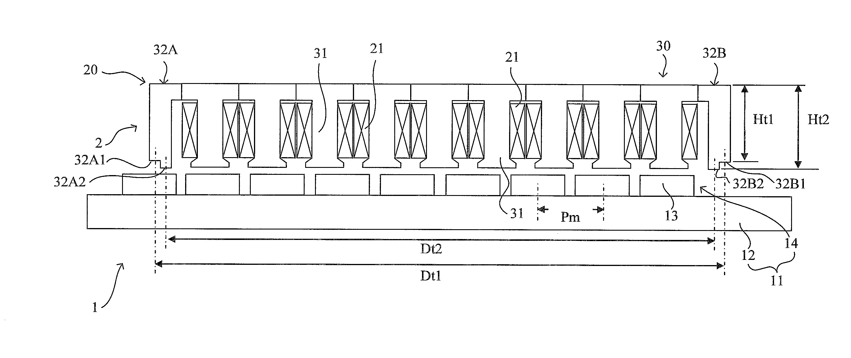
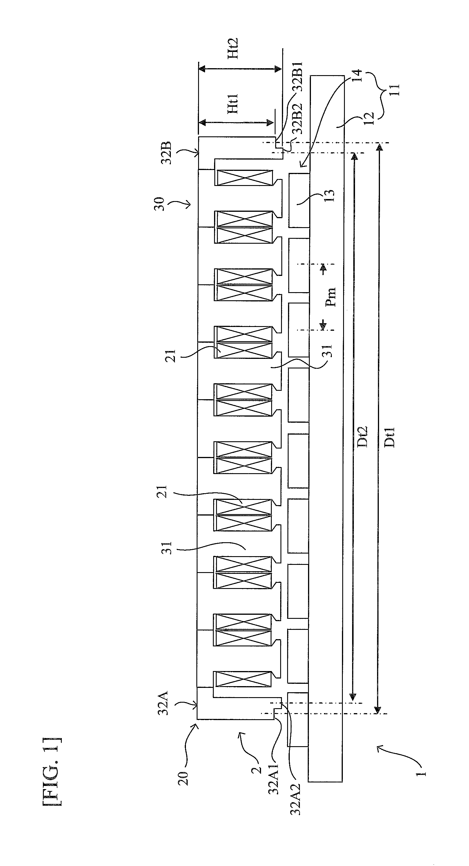
[0023]FIG. 1 is a longitudinal sectional view illustrating the structure of a linear motor according to the embodiment. In FIG. 1, a linear motor 1 of the embodiment comprises a stator 11 and a mover 2 as described above.

[0024]The stator 11 consists of a field system comprising a single field yoke 12 and a magnet series 14 made of a plurality of permanent magnets 13. The series of magnets 14 is linearly arranged on the inside of the field yoke 12 along the direction of travel of the mover 2 with the polarities of the plurality of permanent magnets 13 arranged in an alternating manner. The permanent magnets 13 are also arranged with a predetermined pitch (pole-to-pole distance) Pm between adjacent magnets.

[0025]The mover 2 comprises an armature 20 disposed facing the field system comprising the field yoke 12 and the magnet series 14 with a magnetic air gap therebet...


PUM


Abstract

The disclosure discloses a linear motor comprising: a field system in which a plurality of permanent magnets are linearly arranged: and an armature configured to face said field system and to have an armature core provided with armature windings, said linear motor running along a predetermined direction of travel with either said field system or said armature serving as a mover and the other serving as a stator, wherein: said armature core comprises: auxiliary teeth that are respectively provided on both ends along said direction of travel and around which said armature windings are not wound; and a plurality of main teeth that are provided between said auxiliary teeth, and each of said auxiliary teeth comprises an end portion shape in which a dimension in a teeth height direction orthogonal to said direction of travel is variable along said direction of travel.

Description

CROSS-REFERENCE TO RELATED APPLICATION[0001]The present application claims priority from Japanese Patent Application No. 2010-054384, which was filed on Mar. 11, 2010, the disclosure of which is incorporated herein by reference in its entirety.BACKGROUND OF THE INVENTION[0002]1. Field of the Invention[0003]The present invention relates to a linear motor used, for example, with industrial machine tools, semiconductor packaging equipment, and the like.[0004]2. Description of the Related Art[0005]A linear motor of one prior art has a stator and a mover. In the stator, permanent magnets are arranged with a predetermined pitch (pole-to-pole distance) Pm between adjacent magnets.[0006]With the above configuration, the linear motor introduces a predetermined current corresponding to the position of the armature of the mover to the armature winding, resulting in an electromagnetic effect between the armature windings and the permanent magnets of the stator that causes the mover to move line...

Claims


Application Information

Patent Timeline
Patent Type & Authority Applications(United States)
IPC IPC(8): H02K41/03
CPCH02K1/148H02K2201/03H02K41/031
Inventor KAKIHARA, MASANOBUSHIKAYAMA, TORU
Owner YASKAWA DENKI KK
Why Eureka
Try Eureka