Tunable evanescent-mode cavity filter

Active Publication Date: 2011-10-06
PURDUE RES FOUND INC
View PDF3 Cites 23 Cited by
  • Summary
  • Abstract
  • Description
  • Claims
  • Application Information

AI Technical Summary

Benefits of technology

[0020]The present invention generally provides improvements in tuning filters. According to one aspect of the invention,

Problems solved by technology

While digital technologies and the associated signal processing have enabled the implementation of frequency agility at base-band, the design and implementation of the RF front-end components remain a significant challenge for mobile systems.
Nevertheless, the large volume and high power consumption (0.75-3 W) of YIG based tunable filters hinder their integration into mobile communication systems.
Inherently high-Q resonators loaded

Method used


Image

  • Tunable evanescent-mode cavity filter
  • Tunable evanescent-mode cavity filter
  • Tunable evanescent-mode cavity filter

Examples


Embodiment Construction

[0032]For the purpose of promoting an understanding of the principles of the invention, reference will now be made to the embodiments illustrated in the drawings and specific language will be used to describe the same. It will nevertheless be understood that no limitation of the scope of the invention is thereby intended, such alterations and further modifications in the illustrated device and such further applications of the principles of the invention as illustrated therein being contemplated as would normally occur to one skilled in the art to which the invention relates. The following description is divided into three parts each having its own series of numbered equations.

Part 1

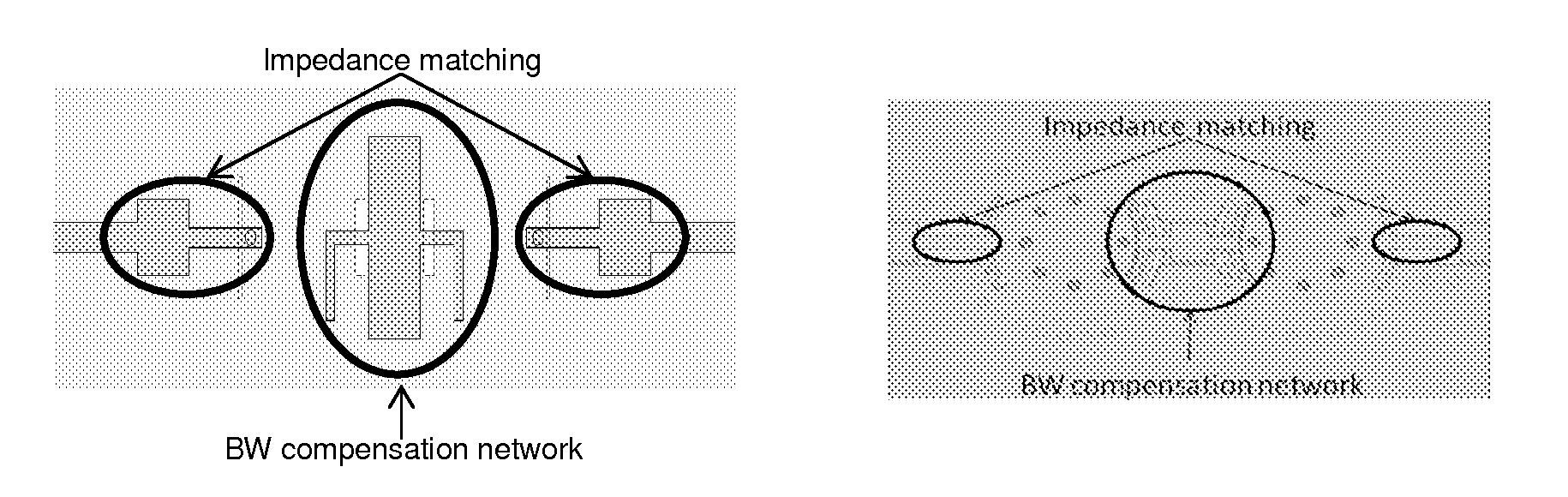
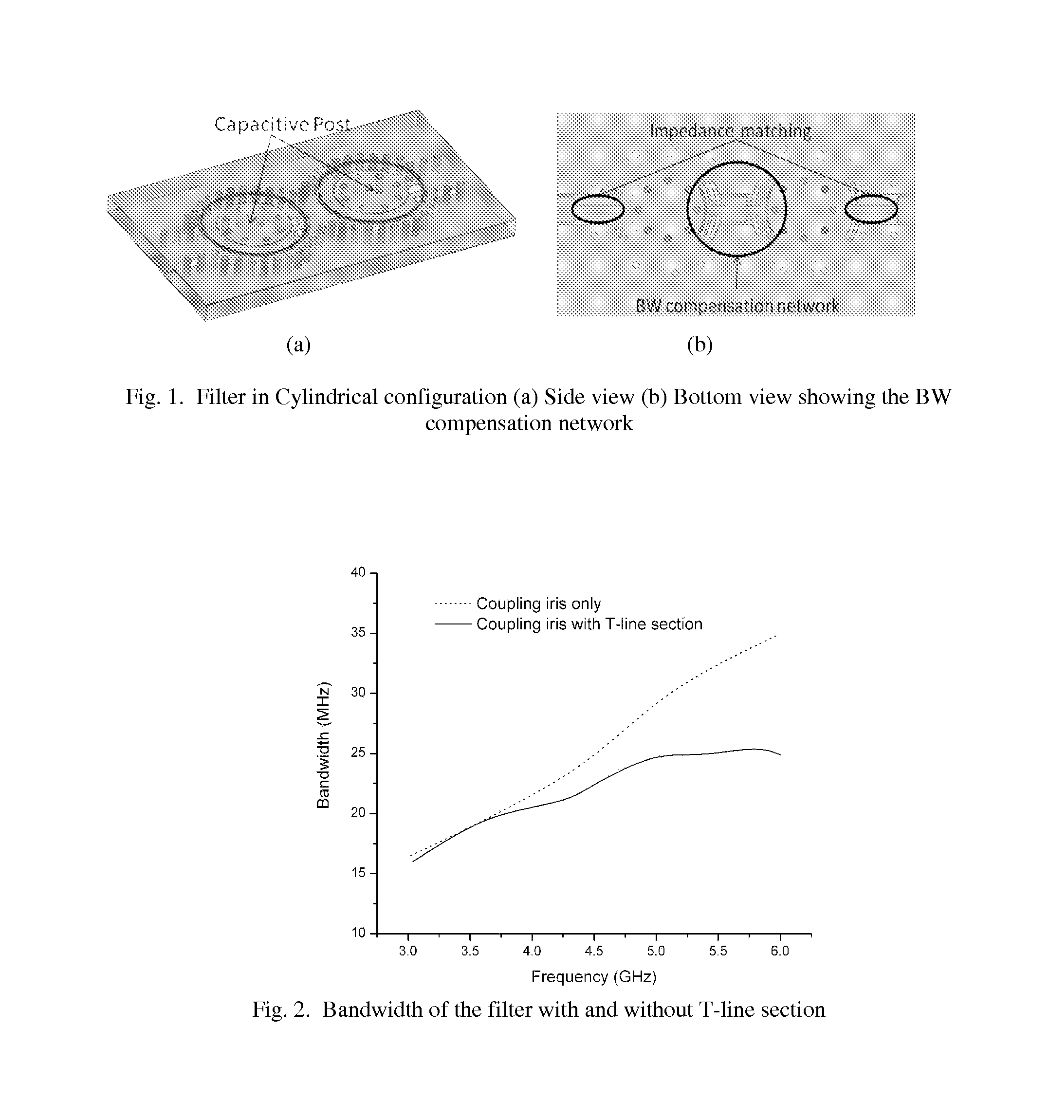
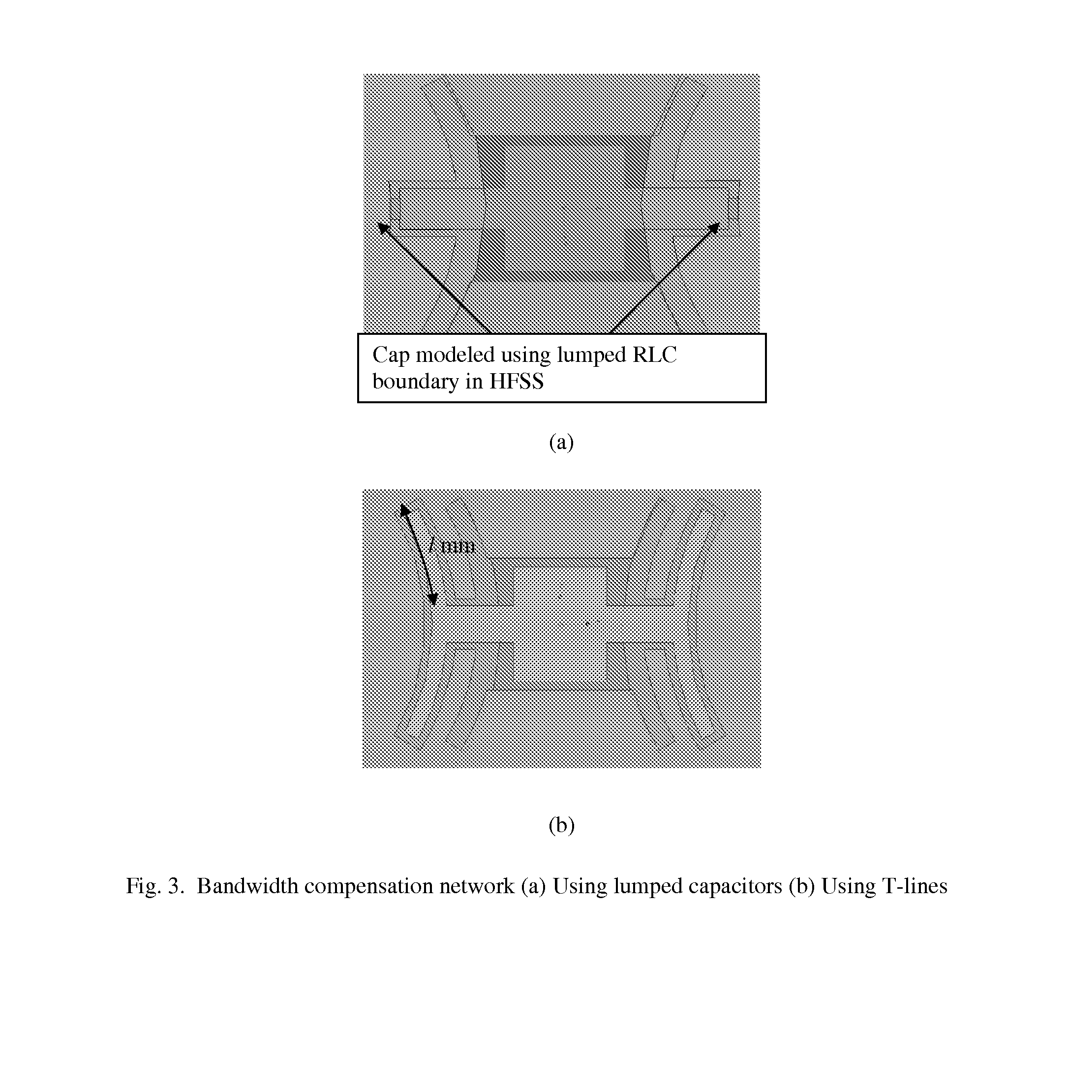
[0033]One preferred embodiment of the present invention is a substrate-integrated, tunable evanescent-mode cavity filter with controllable bandwidth using surface mount varactors. The filter has a bandwidth compensation network that allows reduction / control over the bandwidth of the filter without affecti...


PUM


Abstract

A tunable filter having an electronically tunable center frequency and dynamic bandwidth control over a large tuning range. High-Q continuously tunable evanescent-mode cavity resonators and filters using reliable RF MEMS actuators. One embodiment is a 3.4-6.2 GHz (1.8:1 tuning ratio) continuously tunable electrostatic MEMS resonator with quality factor of 460-530, with a volume of 18×30×4 mm including the actuation scheme and biasing lines. A tunable resonators is also disclosed with a 2.8:1 (5.0-1.9 GHz) tuning ratio, and Q of 300-650.

Description

CROSS-REFERENCE TO RELATED APPLICATION[0001]This application is related to U.S. Provisional Patent Application No. 61 / 102,717, filed Oct. 3, 2009, which application is hereby incorporated by reference along with all references cited therein.BACKGROUND OF THE INVENTION[0002]This invention relates to electronic filters, and more particularly to tunable filters of the type used in radio-frequency (RF) systems such as RF communications and test equipment, for example, in RF front-end sections of receivers and transmitters.[0003]The continuous rapid development of wireless communication technologies has led to significant growth of RF and microwave devices and systems for both civilian and military applications. This is particularly true for mobile applications with increased demands for high efficiency, small volume, low weight and low cost. Furthermore, there is a defining trend to combine multiple wireless communication functionalities into a single frequency-agile platform for multi-...

Claims


Application Information

Patent Timeline
IPC IPC(8): H01P1/207
CPCH01P1/219H01P7/06H01P11/007
Inventor JOSHI, HIMANSHUSIGMARSSON, HJALTI HREINNPEROULIS, DIMITRIOSCHAPPELL, WILLIAM J.LIU, XIAOGUANG
Owner PURDUE RES FOUND INC
Why Eureka
Try Eureka