

Refrigerator having ice transfer unit
- Summary
- Abstract
- Description
- Claims
- Application Information
AI Technical Summary
Benefits of technology
Problems solved by technology
Method used
Image

Examples
Embodiment Construction
[0026]A refrigerator having an ice transfer unit according to an embodiment of the present invention will now be described in detail with reference to the accompanying drawings.
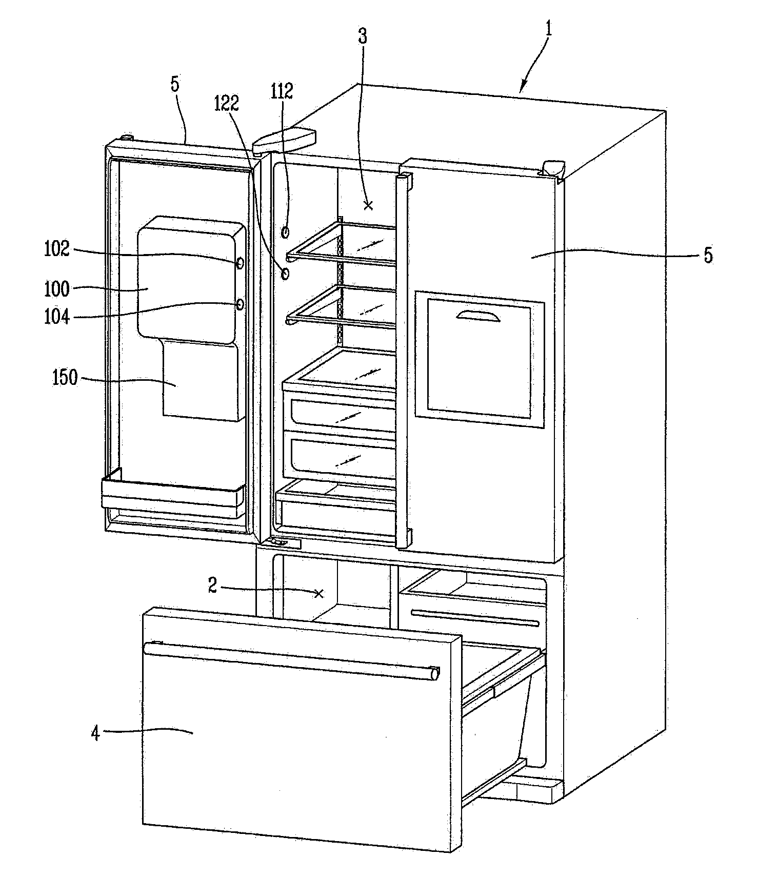
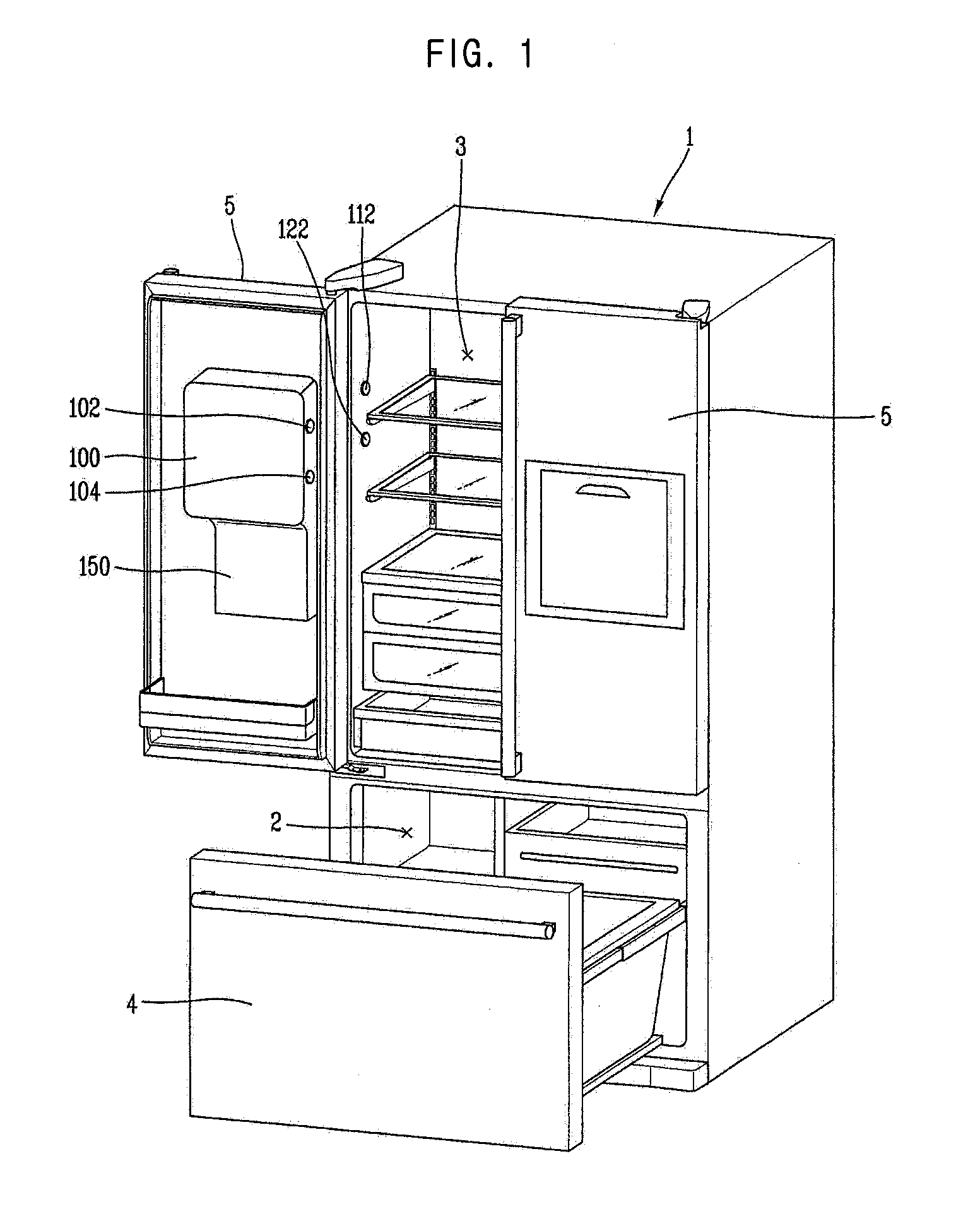
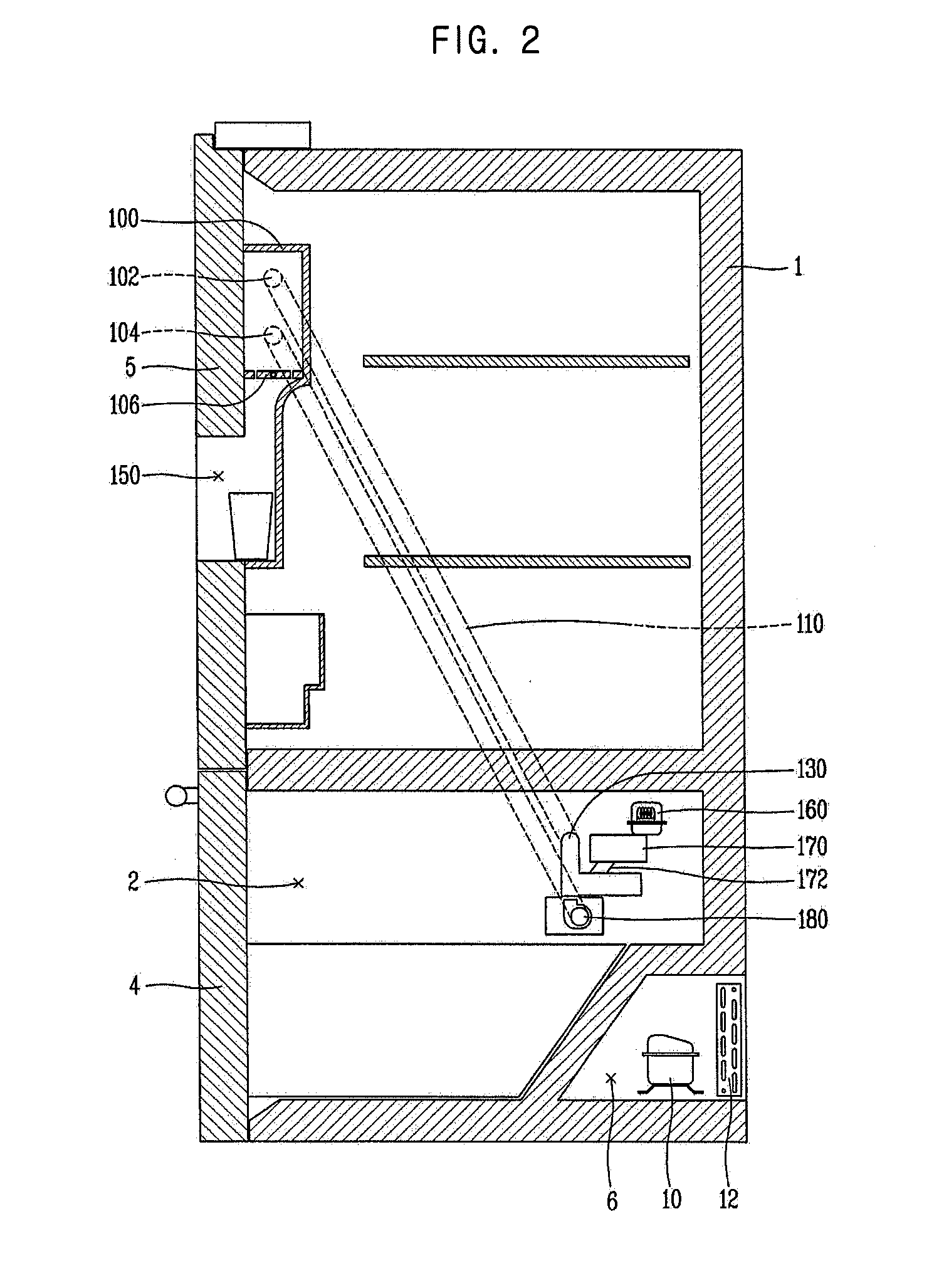
[0027]FIG. 1 is a perspective view of a refrigerator according to an embodiment of the present invention, and FIG. 2 is a vertical sectional view showing an internal structure of the refrigerator of FIG. 1. The refrigerator illustrated in FIG. 1 is a so-called French door type refrigerator in which a refrigerating chamber is disposed at an upper portion and a freezing chamber is disposed at a lower portion, and the refrigerating chamber is opened and closed by two doors. Here, refrigerating chamber does not necessarily have two doors, and the refrigerating chamber may be open or closed by a single door.
[0028]As illustrated, the refrigerator according to an embodiment of the present invention, a freezing chamber 2 for freezing and keeping food items in storage is formed at a lower portion of the refrigerator m...
PUM
 Abstract
Description
Claims
Application Information