

Hand-held and conversion vacuum cleaner with adapter
- Summary
- Abstract
- Description
- Claims
- Application Information
AI Technical Summary
Benefits of technology
Problems solved by technology
Method used
Image

Examples
Embodiment Construction
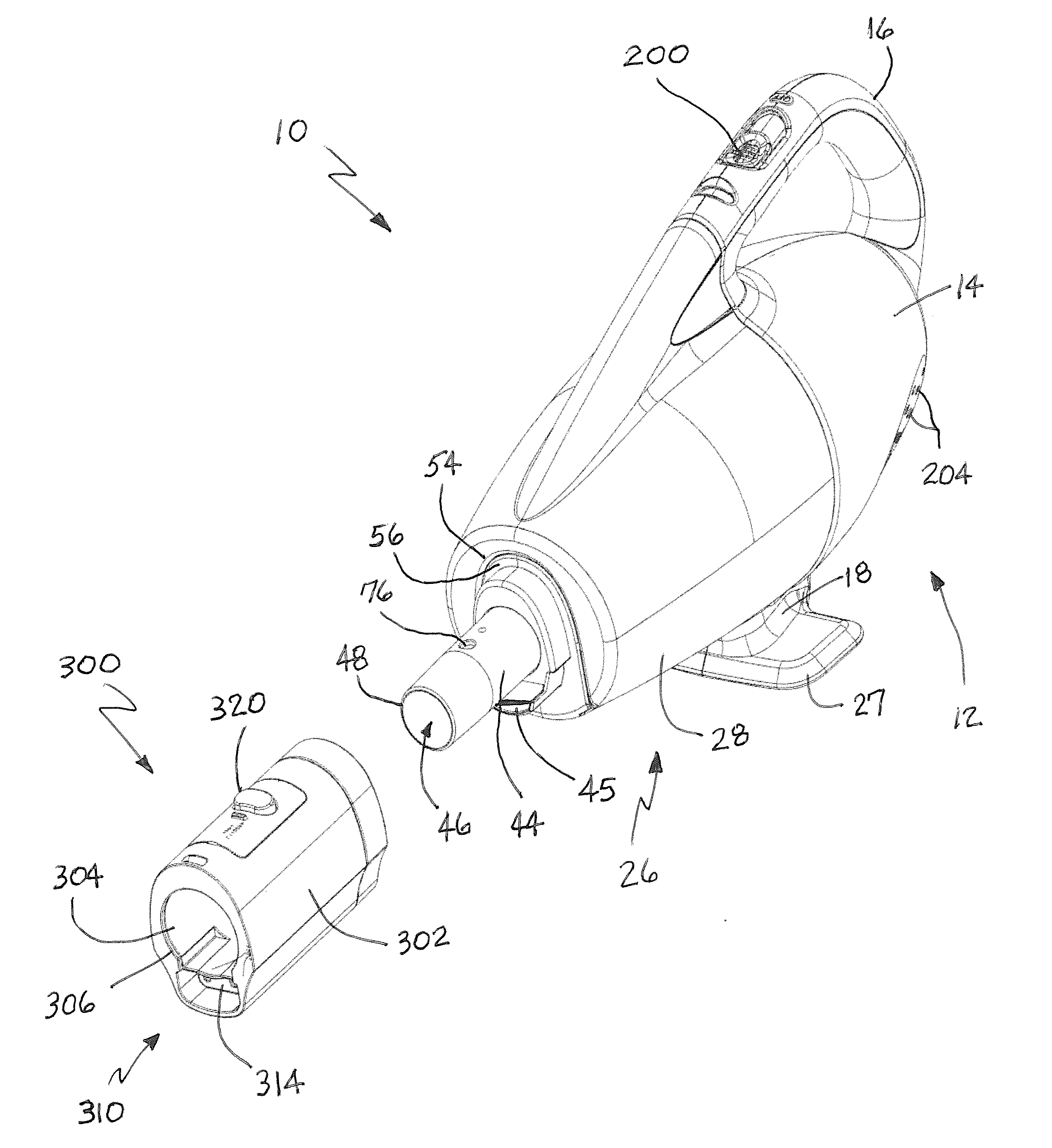
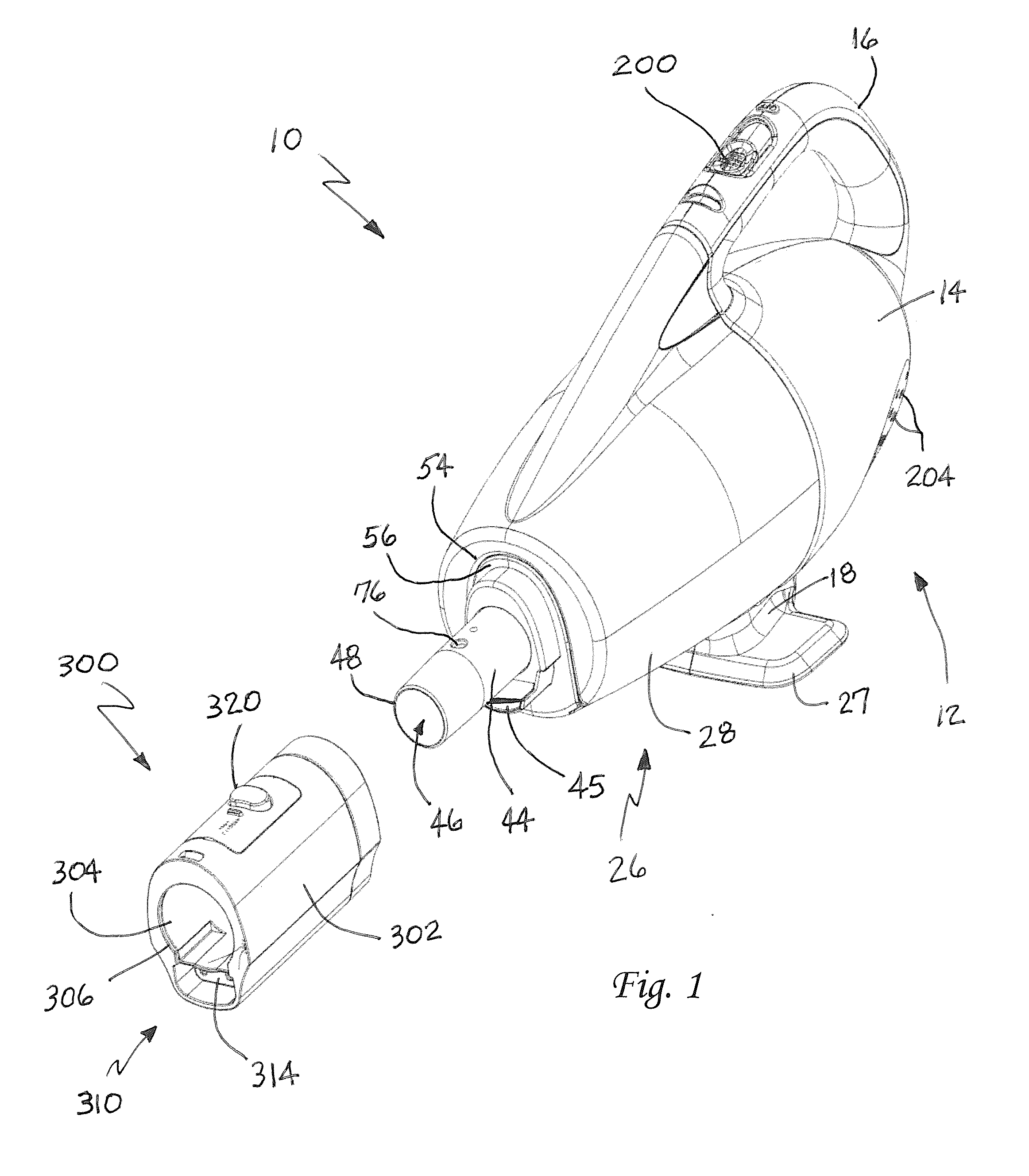
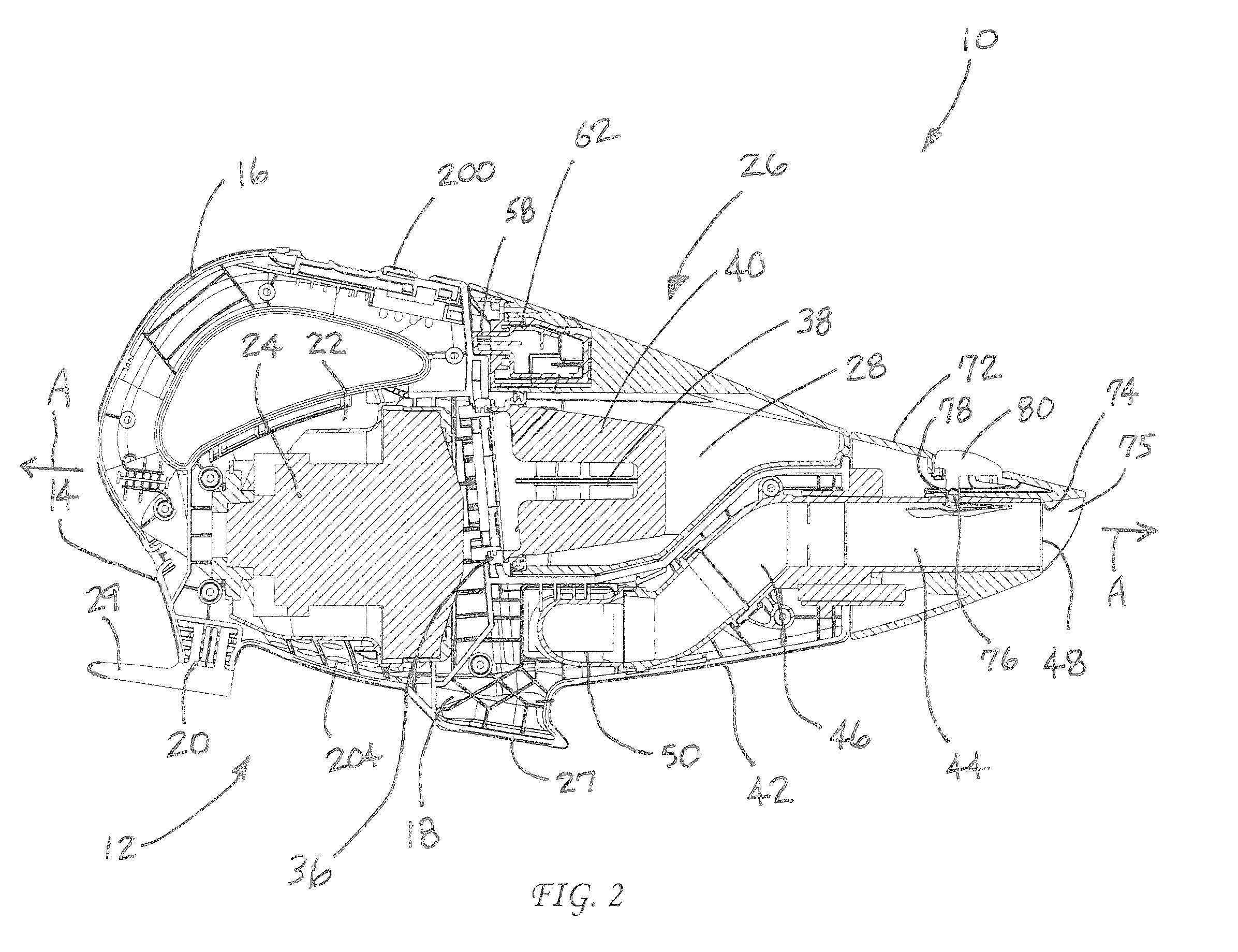
[0022]Reference is now made to FIGS. 1 and 2 illustrating the hand-held and conversion vacuum cleaner 10 of the present invention. The vacuum cleaner 10 includes a housing 12 having a body 14, an integral control handle 16 and two support members 18, 20. The main body 14 of the housing 12 defines a compartment 22 receiving a suction generator 24. As illustrated, the suction generator 24 is positioned beneath the control handle 16 as well as above and between the support members 18, 20. This is done for balance and ease of operation as will be described in greater detail below.
[0023]The vacuum cleaner 10 is powered from a standard electrical wall outlet by means of an electric cord and plug (not shown). Unlike battery powered hand held vacuum cleaners, the vacuum cleaner 10 of the present invention provides high performance cleaning suction that is sustainable indefinitely as required for virtually any cleaning application. When not in use, the cord may be wrapped around and convenie...
PUM
 Abstract
Description
Claims
Application Information