Counter-rotating polisher

Inactive Publication Date: 2012-04-12
HAMMER ELECTRIC POWER TOOLS
View PDF8 Cites 5 Cited by
  • Summary
  • Abstract
  • Description
  • Claims
  • Application Information

AI Technical Summary

Benefits of technology

[0005]A main object of the present invention is to provide a counter-rotating polisher which counter-rotating polishe

Problems solved by technology

Nowadays, a tray of a conventional polisher rotates towards a single direction, this kind of structure does not only have an inferior effect, but also runs unsteadily.
Because of a reacting force of the poli

Method used


Image

  • Counter-rotating polisher
  • Counter-rotating polisher
  • Counter-rotating polisher

Examples


Example

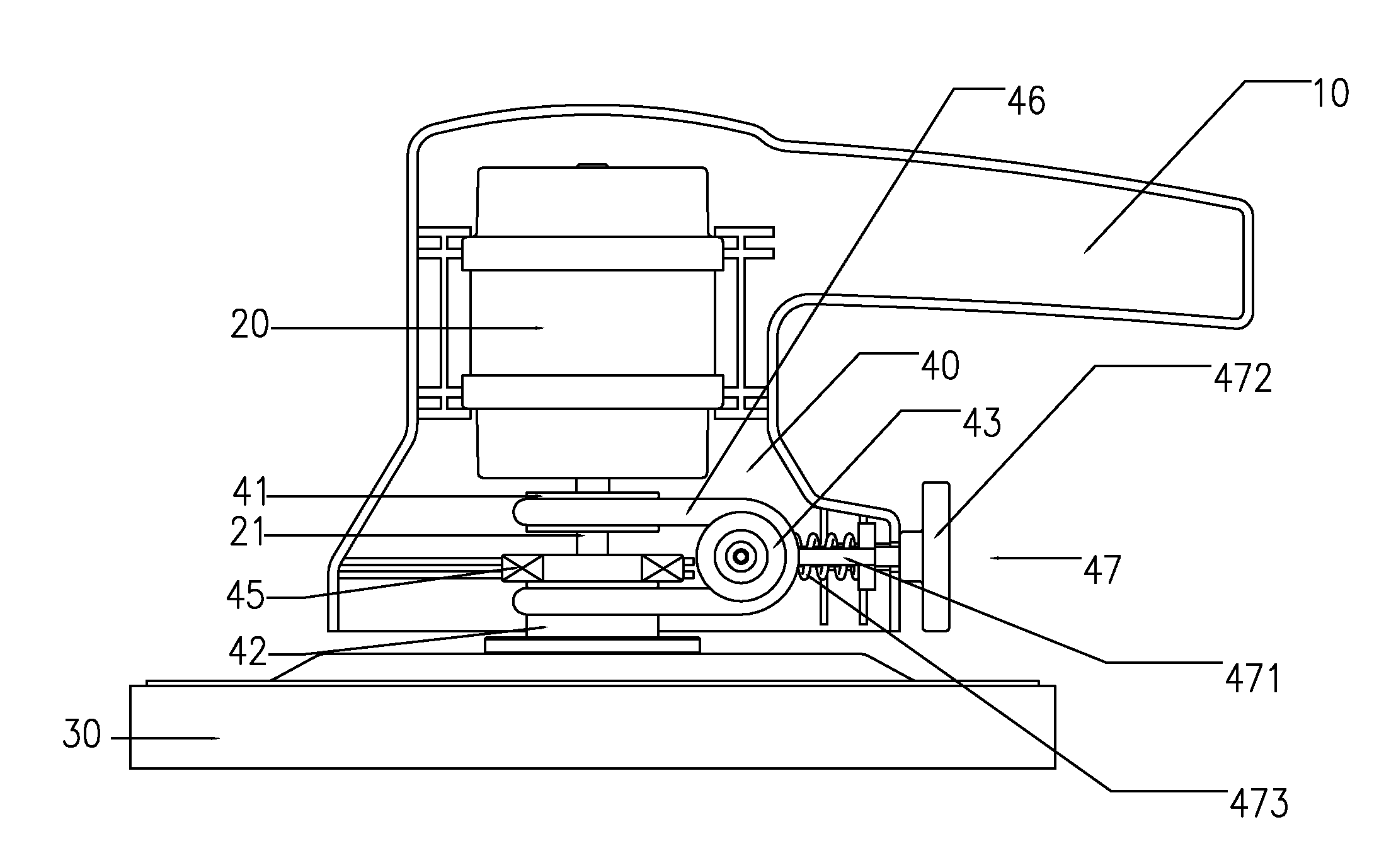
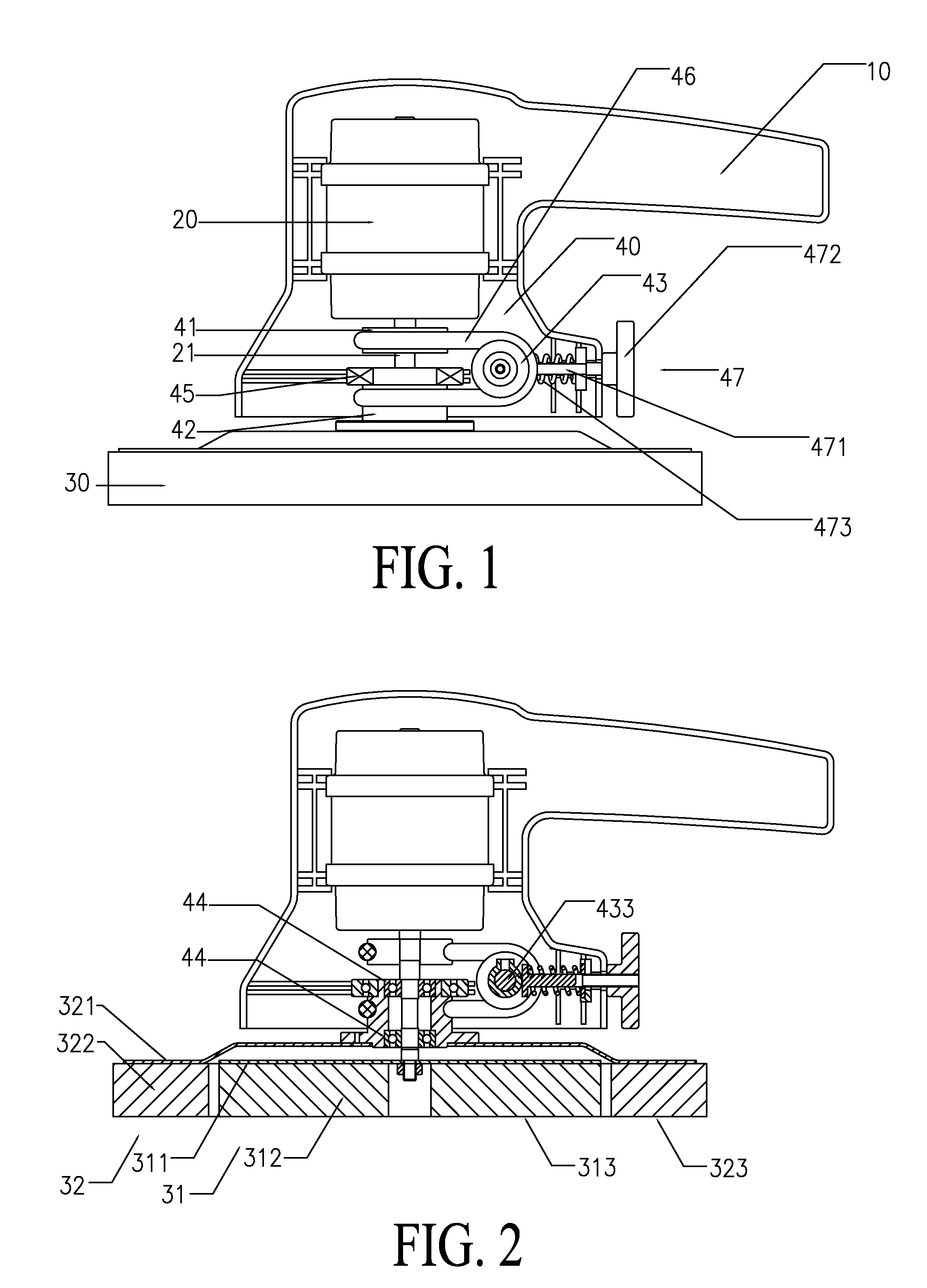
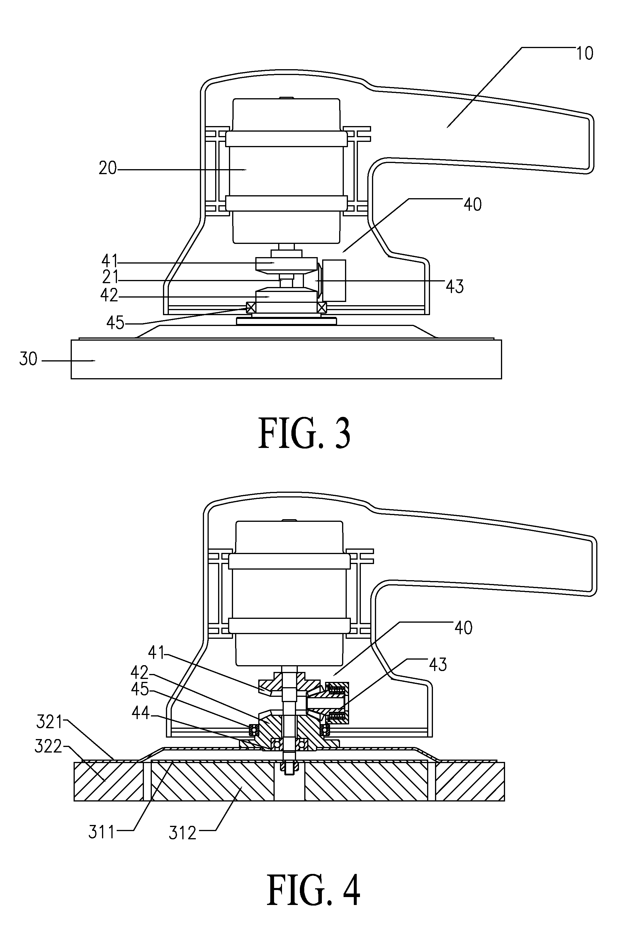
[0027]Referring to FIG. 1 to FIG. 10 of the drawings, the present invention is a counter-rotating polisher, comprising: an enclosure 10, an electric motor 20, a polishing arrangement 30 and a counter-rotating arrangement 40.

[0028]The electric motor 20 is fixed to the enclosure 10, the electric motor 20 comprises a driving axle 21.

[0029]The polishing arrangement 30 comprises a first polishing device 31 and a second polishing device 32. The first polishing device 31 comprises a first fixed tray 311 and a first polishing material 312. The first polishing material 312 is fixedly connected to an outer side of the first fixed tray 311. The first fixed tray 311 is perpendicular to the driving axle 21. The second polishing device 32 comprises a second fixed tray 321, and a second polishing material 322 fixedly connected to an outer side of the second fixed tray 321. The second fixed tray 321 is perpendicular to the driving axle 21. A polishing surface 313 of the first polishing material 312...


PUM


Abstract

A counter-rotating polisher includes: an enclosure, an electric motor, a polishing arrangement and a counter-rotating arrangement. The electric motor is fixed to the enclosure and includes a driving axle. The polishing arrangement includes two polishing device. The polishing devices respectively include a fixed tray and a polishing material that are fixedly connected to an outside of the fixed tray. The fixed tray is perpendicular to the driving axle. The counter-rotating arrangement includes a first driving wheel, a second driving wheel and a change-direction wheel. The first driving wheel is connected to the driving axle and driven by the driving axle. The second driving wheel is fixedly connected to the second fixed tray. The change-direction wheel is connected to the first driving wheel and the second driving wheel. The driving axle rotates the first polishing material positively. The change-direction wheel reversely transmits the rotation to the second driving wheel.

Description

BACKGROUND OF THE PRESENT INVENTION[0001]1. Field of Invention[0002]The present invention relates to a polisher, and more particularly to a counter-rotating polisher.[0003]2. Description of Related Arts[0004]Polishers are used in many industries and occasions. Nowadays, a tray of a conventional polisher rotates towards a single direction, this kind of structure does not only have an inferior effect, but also runs unsteadily. Because of a reacting force of the polished object, the polisher is always under a single direction force in operating, so a person is needed to fix a position of the polisher, especially a long time operating will bring the person hands fatigue.SUMMARY OF THE PRESENT INVENTION[0005]A main object of the present invention is to provide a counter-rotating polisher which counter-rotating polishes at the same time, the reacting forces of the polishing object are counteracted, and does not need to fix specially.[0006]Another object of the present invention is to prov...

Claims


Application Information

Patent Timeline
IPC IPC(8): B24B55/00
CPCB24B23/03B24B23/02
Inventor HUANG, JIANCHUWANG, KEWEIZHU, KUNYUANXU, XIAOPINGZHU, LIGANG
Owner HAMMER ELECTRIC POWER TOOLS
Why Eureka
Try Eureka