Drainage circuit for draining liquid coming from a power plant of a rotorcraft, the circuit incorporating an appliance for monitoring an excessive flow of the liquid

a technology for draining circuits and power plants, applied in the field of aircraft, can solve problems such as general problems of monitoring and maintaining the power plant, leakage of liquid, and analogous circuits associated with conveying liquid, and achieve the effect of convenient installation

Inactive Publication Date: 2013-08-08
EUROCOPTER
View PDF21 Cites 8 Cited by
  • Summary
  • Abstract
  • Description
  • Claims
  • Application Information

AI Technical Summary

Benefits of technology

[0067]The predisposition of the drainage circuit of the present invention to monitoring a leakage liquid conveyed from a power plant of a rotorcraft and/or its nearby environment to the environment outside the rotorcraft, does not prejudice in any way other analogous applications that could be made thereof. The proposed structure for the drainage circuit of the present invention makes it easy to adapt to analogous other applications associated with monitoring the quantity of a liquid flowing through a drainage circuit and coming from a leakage source of said liquid from a

Problems solved by technology

Under such conditions, there arises the general problem of monitoring and maintaining the power plant.
The leaktightness of members making use of a liquid, and analogously of any circuits associated with conveying the liquid,

Method used


Image

  • Drainage circuit for draining liquid coming from a power plant of a rotorcraft, the circuit incorporating an appliance for monitoring an excessive flow of the liquid
  • Drainage circuit for draining liquid coming from a power plant of a rotorcraft, the circuit incorporating an appliance for monitoring an excessive flow of the liquid
  • Drainage circuit for draining liquid coming from a power plant of a rotorcraft, the circuit incorporating an appliance for monitoring an excessive flow of the liquid

Examples


Embodiment Construction

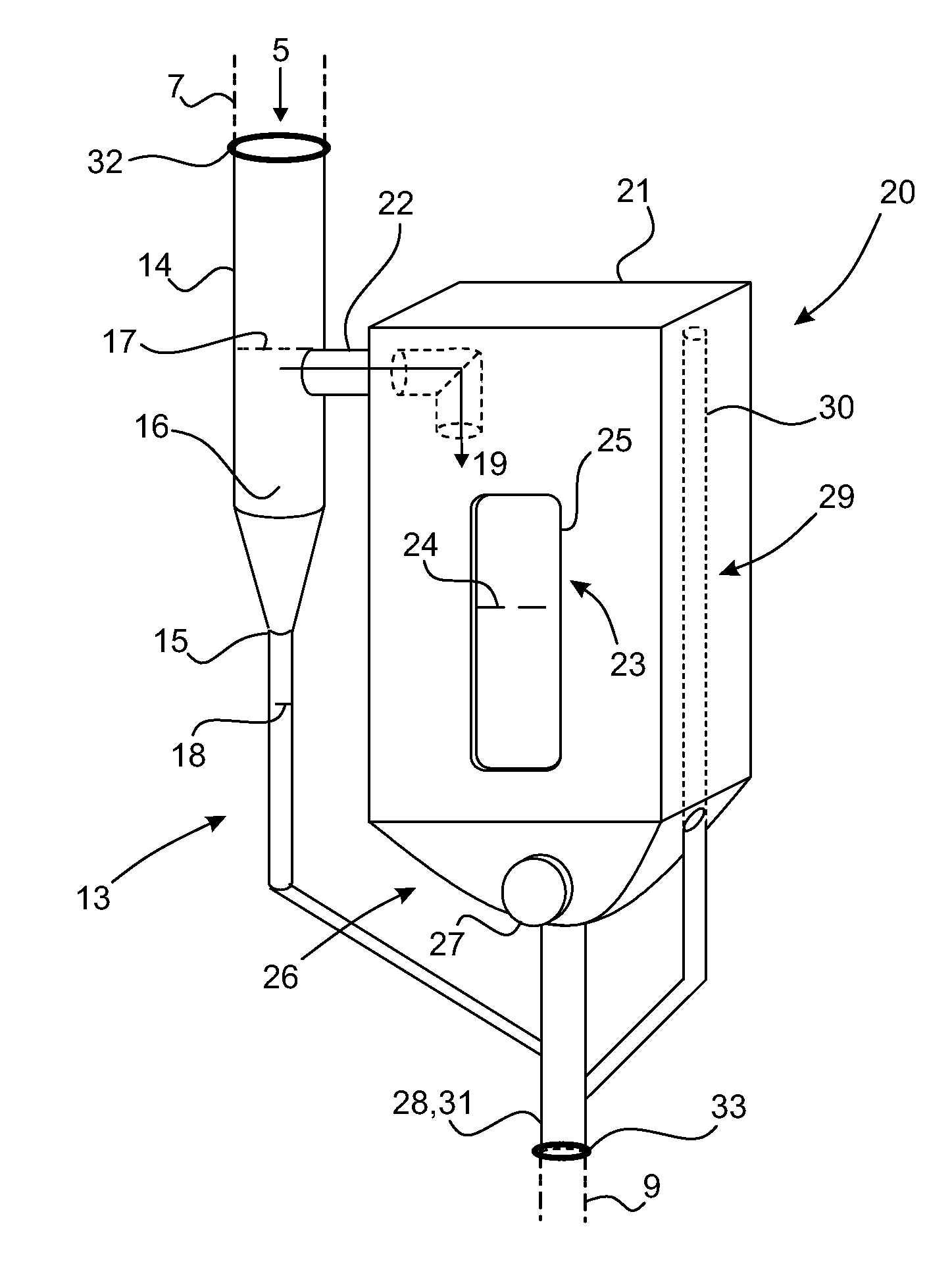
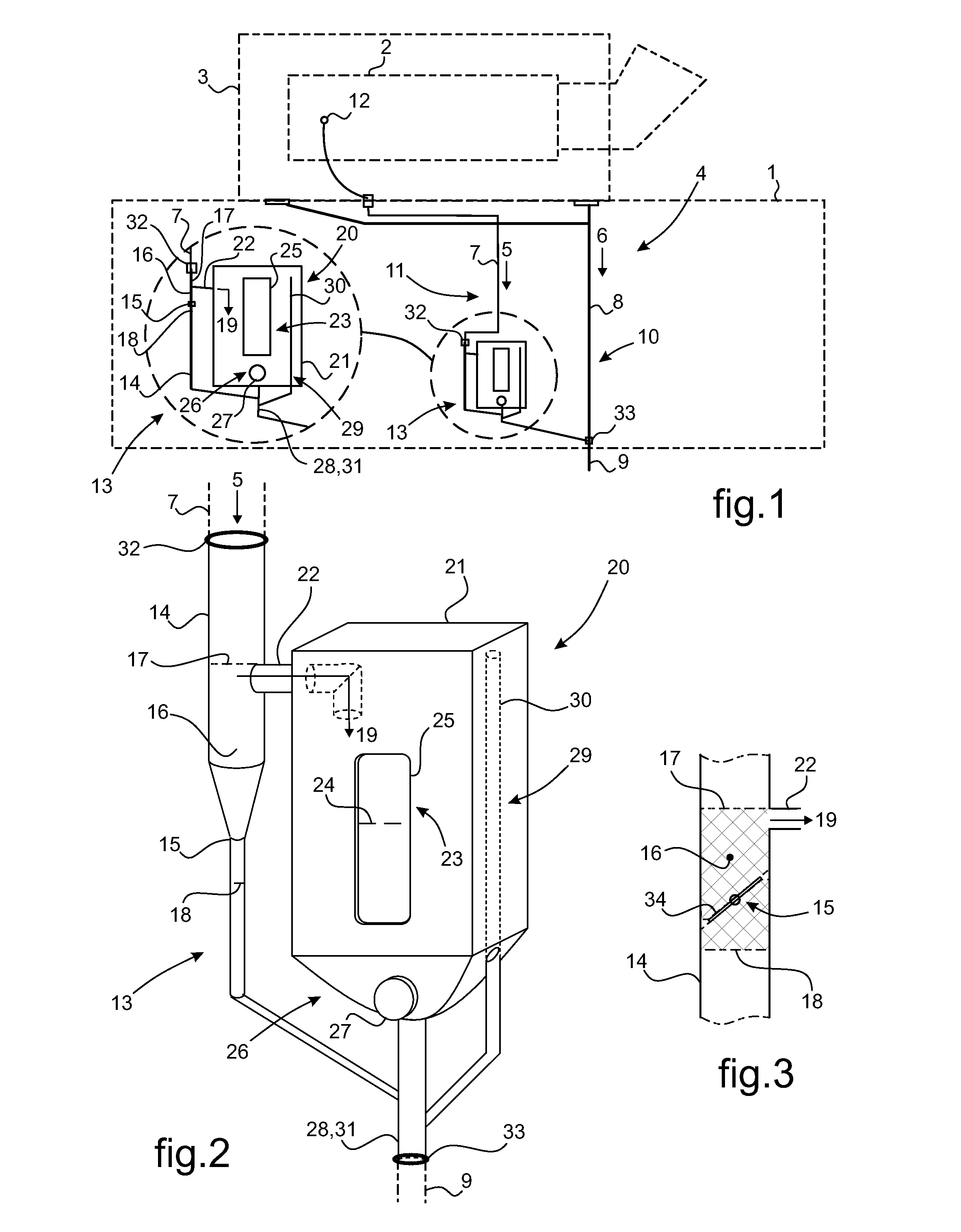
[0085]In FIG. 1, a rotorcraft 1 is fitted with a power plant 2 housed in a compartment 3 of the rotorcraft 1. The rotorcraft 1 has a drainage circuit 4 for draining liquids 5, 6 under natural flow, the circuit comprising various ducts, including at least one upstream duct 7, 8 and at least one downstream duct 9.

[0086]The upstream duct(s) 7, 8 is / are for collecting and conveying liquids 5, 6 from the power plant 3 to a downstream duct 9 for discharging the collected liquids 5, 6 to the outside. An individual drainage circuit 10 is allocated to discharging runoff water 6 that might stagnate in the bottom of the compartment 3 housing the power plant 2. At least one other individual drainage circuit 11 is allocated to discharging a functional fluid 5 coming from a leaking liquid source 12, in particular from a member of the power plant 2.

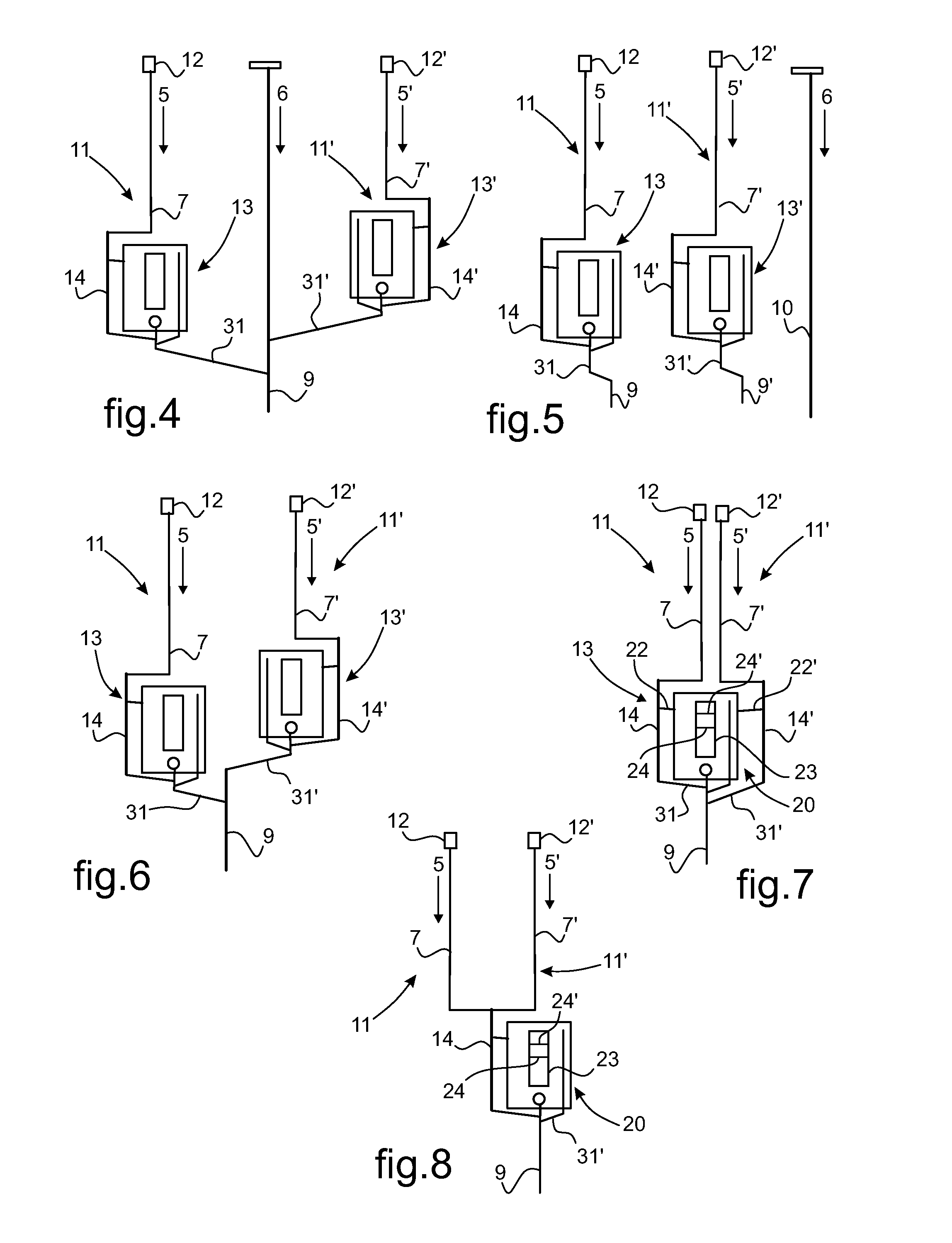
[0087]The individual drainage circuit 11 allocated to discharging the functional liquid 5 is fitted with a monitoring appliance 13 for monitoring the q...


PUM


Abstract

The invention relates to a drainage circuit (4) for a flow of a liquid (5), the circuit being fitted with a monitoring appliance (13) for monitoring an excess flow rate of the liquid (5). The monitoring appliance (13) comprises a monitoring duct (14) interposed between an upstream duct (7) for collecting the liquid (5) and a downstream duct (9) for discharging the liquid (5). The monitoring duct (14) has retaining means (15) for retaining part of the liquid (5) inside a chamber (16) arranged to receive a spillway (22) of the captured liquid (19) in a reserve (20) fitted with indicator means (23) with a visual scale for providing warning information relating to the quantity of liquid (24) contained in the reserve (20).

Description

CROSS REFERENCE TO RELATED APPLICATIONS[0001]This application claims priority to French patent application No. FR 12 00375 filed on Feb. 8, 2012, the disclosure of which is incorporated in its entirety by reference herein.BACKGROUND OF THE INVENTION[0002](1) Field of the Invention[0003]The present invention relates to the field of aircraft, and in particular rotorcraft, and it relates more particularly to on-board equipment for monitoring the operation of a power plant fitted to such an aircraft. The present invention relates more specifically to drainage circuits for a flow of at least one liquid coming from a power plant fitted to a rotorcraft, and leading to discharge to the outside environment.[0004](2) Description of Related Art[0005]Rotorcraft are fitted with one or more power plants for driving rotation of at least one rotor, or indeed for driving at least one accessory of the rotorcraft. The power plant is generally installed in a compartment of the rotorcraft airframe. Such...

Claims


Application Information

Patent Timeline
IPC IPC(8): G08B21/18
CPCG01M3/26G08B21/182Y10T137/8342Y10T137/8326Y10T137/2071Y10T137/2065
Inventor MOUGIN, STEPHANECATTEAU, JEAN-SEBASTIEN
Owner EUROCOPTER
Why Eureka
Try Eureka