Protective apparatuses for rotary control knobs

Inactive Publication Date: 2014-08-28
MESSADEK KARIM
View PDF6 Cites 5 Cited by
  • Summary
  • Abstract
  • Description
  • Claims
  • Application Information

AI Technical Summary

Benefits of technology

The present invention aims to provide a protective function to prevent accidental operation of a rotary knob, while still allowing it to be intentionally operated. The device is designed to be easy to use and manufacture.

Problems solved by technology

Stepping on the on / off foot-switch without inadvertently disturbing or stepping on the control knobs can therefore be a challenging task.
This challenge is even greater if the pedal sits in between other pedals on a tightly packed pedal-board.
There is always a risk of accidentally disturbing the adjacent control knob's setting, and this scenario is simply not acceptable in the middle of a stage performance.
Control knobs settings can also be disturbed when musicians transport their effects pedals or pedal-boards inside light-weight soft bag (sometimes referred to as “gig bags”).
The friction between the inner surfaces of the bag and the pedals often causes the control knobs to inadvertently move during transport, forcing the musicians to constantly reset the knobs positions before using the pedals.
However, an ‘on the fly’ operation of the control knob is impossible, since it requires the user to first unlock the locking device, set the knob position, and then re-lock the locking device.
They typically have a handful of seconds to tweak several knobs, which is impractical with these locking systems in place.
Additionally, these locking devices do not provide any protection to the control knobs themselves and thus the knobs may fall off or otherwise become inadvertently damaged.
Unfortunately, many touring musicians tend to use duct tape and the like to secure their control knob settings.
However, Stomplock™ cannot be applied to individual knobs and is suffers from the same set-and-forget solution drawbacks mentioned above.

Method used


Image

  • Protective apparatuses for rotary control knobs
  • Protective apparatuses for rotary control knobs
  • Protective apparatuses for rotary control knobs

Examples


Embodiment Construction

[0037]The terminology used herein is for the purpose of describing particular embodiments only and is not intended to be limiting of the invention. As used herein, the term “and / or” includes any and all combinations of one or more of the associated listed items. As used herein, the singular forms “a,”“an,” and “the” are intended to include the plural forms as well as the singular forms, unless the context clearly indicates otherwise. It will be further understood that the terms “comprises” and / or “comprising,” when used in this specification, specify the presence of stated features, steps, operations, elements, and / or components, but do not preclude the presence or addition of one or more other features, steps, operations, elements, components, and / or groups thereof.

[0038]Unless otherwise defined, all terms (including technical and scientific terms) used herein have the same meaning as commonly understood by one having ordinary skill in the art to which this invention belongs. It wi...


PUM


Abstract

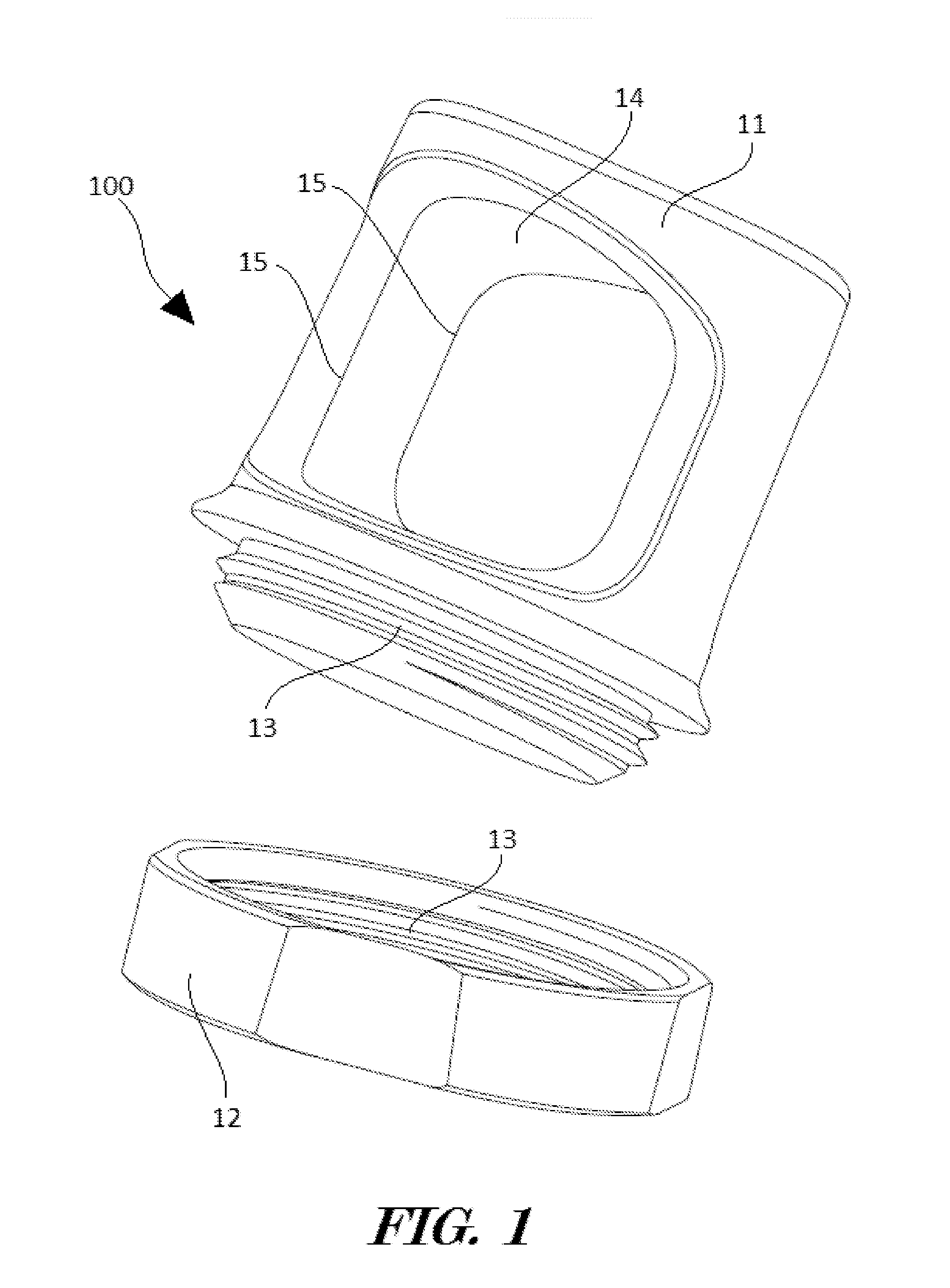
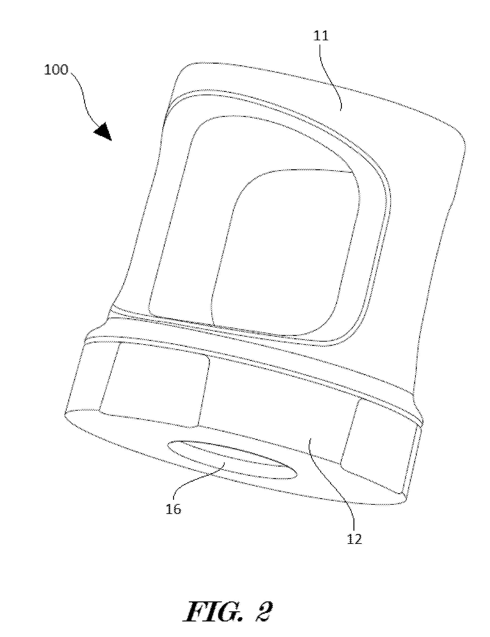
It is one aspect of the present invention to provide novel protective apparatuses for rotary control knobs and the like configured to limit unintentional manipulation of a control actuator, such as a rotary knob, on an electronic device. In preferred embodiments, the apparatus comprises a cover member, coupling device, and a plate member configured to be secured to an electronic device. The cover member is configured to encase or surround a control actuator and to be engaged to the plate member by a coupling device. The coupling device may provide a temporary or permanent engagement between the cover member 11 and the plate member 12.

Description

CROSS REFERENCES TO RELATED APPLICATION[0001]The present application claims priority to co-pending U.S. provisional patent application No. 61 / 767,887 filed Feb. 22, 2013, and entitled “SAFETY DEVICE FOR ROTARY CONTROL KNOBS” the entire contents of which are incorporated by reference herein.FIELD OF THE INVENTION[0002]The present invention relates to the field of rotary knob protective and enhancing apparatuses. More specifically, the invention relates to apparatuses configured to limit rotational access to a knob.BACKGROUND[0003]Foot operated effects pedals (sometimes referred to as “stomp boxes”) are frequently used by guitarists and other musicians to modulate or alter the sound of a musical instrument. They typically consist of an electronic circuit housed inside a relatively small enclosure, and a plurality of control knobs, foot-switches, toggle-switches, connectors, and the like.[0004]The electronic circuit processes the incoming instrument signal before outputting it to an am...

Claims


Application Information

Patent Timeline
IPC IPC(8): G10H1/32
CPCG10H1/32G05G1/08G05G5/005Y10T428/13Y10T29/49716
InventorMESSADEK, KARIM
OwnerMESSADEK KARIM