Multi-cyclone collector

a collector and multi-cyclone technology, applied in the direction of separation process, filtration separation, vortex flow apparatus, etc., can solve the problems of uneconomical maintenance or replacement of nonwoven fabrics, failure to achieve high-efficiency separation, and reduced processable air volume, etc., to achieve high collection efficiency, high accuracy, and sufficient air volume

Active Publication Date: 2014-10-16
HORKOS
View PDF1 Cites 17 Cited by
  • Summary
  • Abstract
  • Description
  • Claims
  • Application Information

AI Technical Summary

Benefits of technology

[0026]One or more embodiments of the present invention enables provision of a multi-cyclone collector that does not rescatter contaminating particles and achieves high accuracy, sufficient air volume, and high collection efficiency.

Problems solved by technology

However, the nonwoven fabric causes clogging and its processable air volume is reduced gradually in the course of time.
Maintenance or replacement of the nonwoven fabric is thus required uneconomically.
However, many of these collectors fail in highly accurate separation and exert insufficient collection performance.
However, a conventional cyclone has a large cyclone radius and low separation accuracy, and is thus utilized as preprocessing devices.
In this case, there arise disadvantages such as clogging and large pressure loss (see Patent Literatures 1 to 3, for example).
A cyclone is restricted due to so-called similarity in design, and decrease in cyclone radius inevitably leads to decrease in size of an inlet port for an air flow.

Method used


Image

  • Multi-cyclone collector
  • Multi-cyclone collector
  • Multi-cyclone collector

Examples


Embodiment Construction

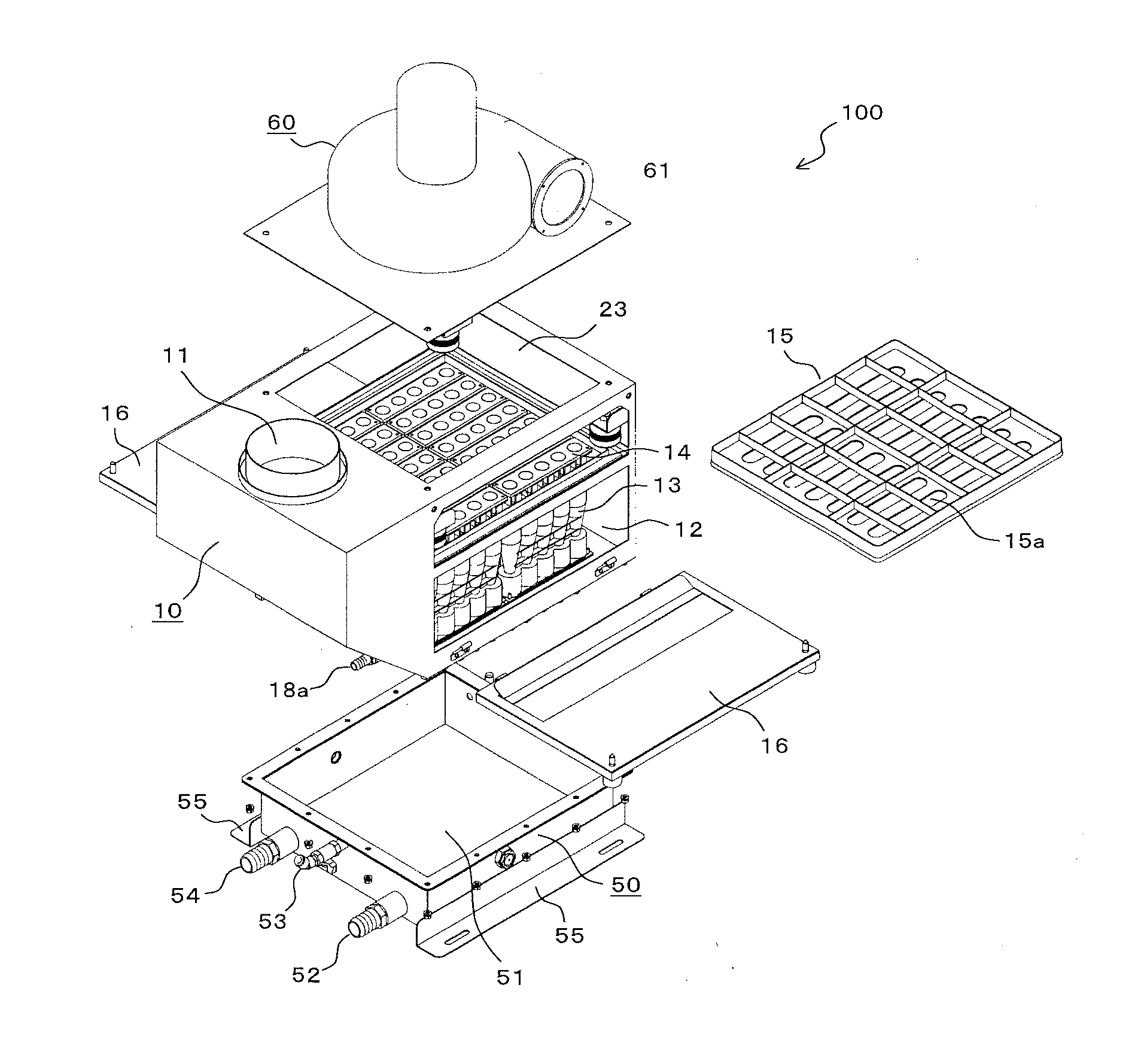
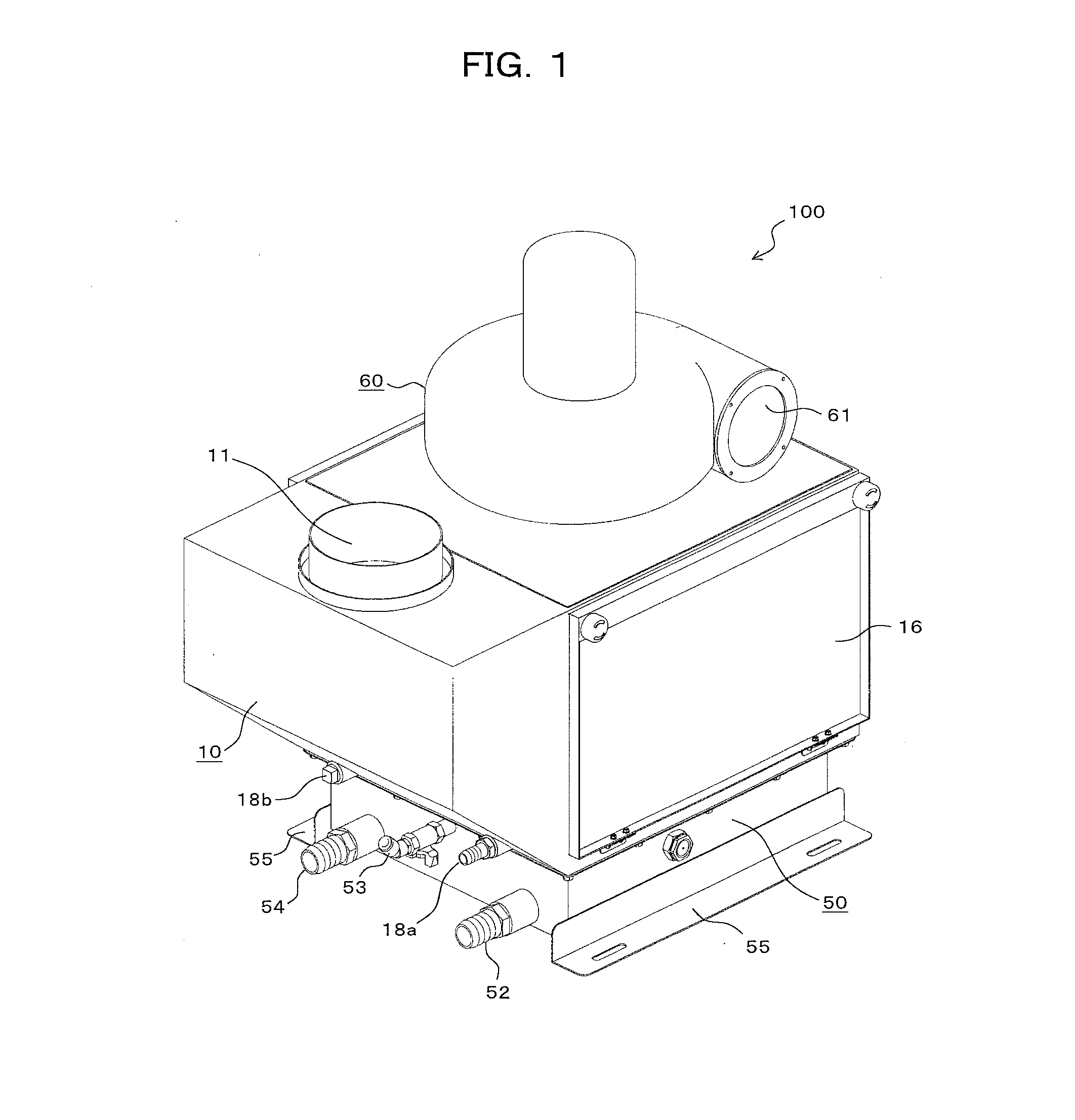
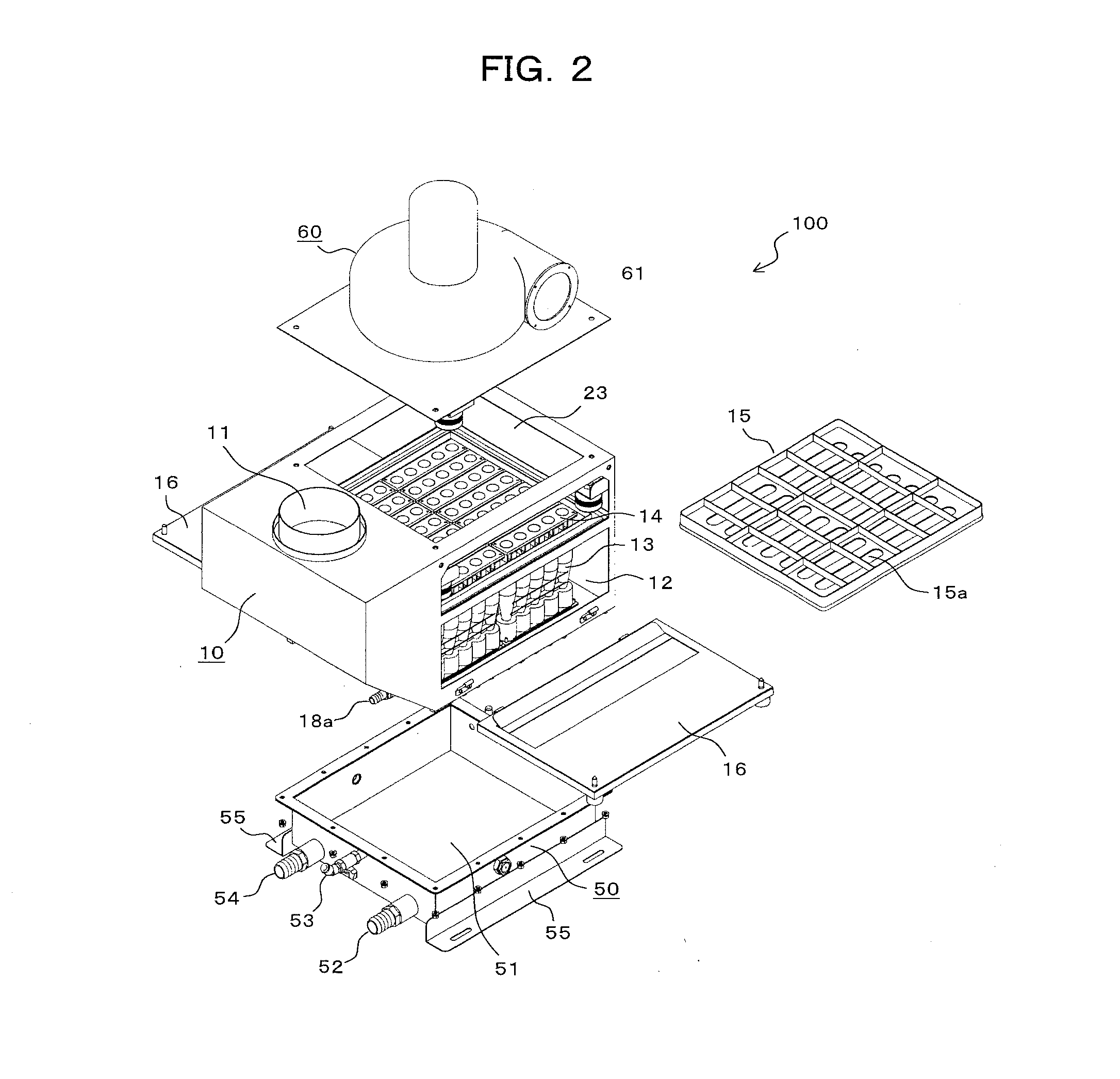
[0048]In embodiments of the invention, numerous specific details are set forth in order to provide a more thorough understanding of the invention. However, it will be apparent to one with ordinary skill in the art that the invention may be practiced without these specific details. In other instances, well-known features have not been described in detail to avoid obscuring the invention. Embodiments of the present invention will be described hereinafter with reference to the drawings. In the respective drawings, identical portions or corresponding portions are denoted by identical reference signs. Exemplified herein is a multi-cyclone collector (hereinafter, referred to as an “oil mist collector”) for collecting oil mist generated during processing of a machine tool.

[0049]An entire structure of the oil mist collector according to one or more embodiments is initially described with reference to FIGS. 1 to 3. As shown in FIGS. 1 and 2, an oil mist collector 100 includes a main body 10,...


PUM

PropertyMeasurementUnit
liquid levelaaaaaaaaaa
air volumeaaaaaaaaaa
inertial forceaaaaaaaaaa

Abstract

A multi-cyclone collector includes a suction port for sucking an air flow including contaminating particles, a cyclone accommodation chamber allowing the air flow sucked through the suction port to be guided thereinto, a plurality of cyclones each accommodated in the cyclone accommodation chamber, for transforming the air flow taken in to a downward swirl flow, separating the contaminating particles, then reversing the swirl flow to the upward swirl flow and releasing the upward swirl flow as a purified air flow, a cyclone exit chamber provided above the cyclone accommodation chamber, that allows the purified air flow from the cyclones to be guided thereinto, and a drain discharge chamber provided below the cyclone accommodation chamber, for collecting the contaminating particles separated by the cyclones.

Description

CROSS-REFERENCE TO RELATED APPLICATIONS[0001]This application is a National Stage application of International Patent Application No. PCT / JP2013 / 005549, filed on Sep. 20, 2013, which claims priority pursuant to 35 U.S.C. §119(a) to Japanese Patent Application No. 2012-228480, filed on Oct. 15, 2012. Both priority applications are hereby incorporated by reference in their entirety.BACKGROUND OF THE INVENTION[0002]1. Field of the Invention[0003]One or more embodiments of the present invention relates to an apparatus for collecting contaminating particles included in an air flow with a plurality of cyclones, and particularly relates to a multi-cyclone collector suitable for separating and collecting oil mist generated during processing of a machine tool.[0004]2. Background Art[0005]Conventional collectors for separating and collecting oil mist include filter apparatuses for filtrating with nonwoven fabric. However, the nonwoven fabric causes clogging and its processable air volume is r...

Claims


Application Information

Patent Timeline
Patent Type & Authority Applications(United States)
IPC IPC(8): B04C5/14B04C5/23B04C5/28
CPCB01D45/12B04C5/14B04C11/00B04C5/28B04C5/23B04C5/24
Inventor NAKAMURA, YUSUKE
Owner HORKOS
Why Eureka
Try Eureka