Electronic Timepiece and Movement

a technology of electronic timepiece and movement, applied in the direction of electric winding, instruments, horology, etc., can solve the problems of inconvenient correction of other chronograph hands, inability to change the measurement condition of rotation signal and correction quantity, and inability to perform delicate correction satisfying a user's intention

Active Publication Date: 2015-09-10
SEIKO EPSON CORP
View PDF6 Cites 44 Cited by
  • Summary
  • Abstract
  • Description
  • Claims
  • Application Information

AI Technical Summary

Problems solved by technology

However, when it is necessary to perform a button operation without using an axial position of the crown in order to switch from the existing information to the correction-targeted information, the electronic timepiece disclosed in JP-A-2008-134129 cannot change the measurement condition of the rotation signal and the correction quantity when the crown is rotatably operated, thereby causing a problem in that delicate correction satisfying a user's intention cannot be performed.
Therefore, even if the correction target is changed by performing the button operation, it is not possible to change the measurement condition of the rotation signal and the correction quantity.
For this reason, if the user performs setting suitable for the correction of any chronograph hand, there is a problem in that the correction of other chronograph hands becomes inconvenient.
Consequently, the hour chronograph hand is rotated multiple times, thereby causing a problem in that a user has difficulty in aligning the hour chronograph hand with the reference position.
Without being limited to the indicating hand, this problem is common to a case where a display unit such as a calendar wheel is corrected by performing a rotary operation of an operation member such as the crown.
Therefore, when the crown is rotated at the zero stage position, the user feels the sense of resistance and may misunderstand that the input has been performed in spite of the fact that any input has not been performed.
In addition, if the user feels the sense of resistance at the zero stage position where no input is performed, the sense of resistance may cause a possibility that the user cannot determine whether or not the input is performed.
Consequently, even if the user feels the sense of resistance by rotating the crown at positions (first stage position and second stage position) other than the zero stage position where the input is performed, the user cannot intuitively determine that the input is performed.
For this reason, usability becomes poor.
However, since these electronic timepieces have multiple functions, the user needs to use multiple input devices in order to manually set the time zone.
Therefore, there is a problem in that it is difficult to perform the input operation for manually setting the time zone.
On the other hand, when the total correction quantity of the display information is as large as 60 to 720, or when the correction time period required for the total correction quantity is as long as five seconds or longer than five seconds, if the display unit is corrected as much as the continuous correction quantity which is suitable for the information whose total correction quantity is small, one-time continuous correction operation may result in insufficiently corrected quantity.
Accordingly, correction operability becomes poor.
For example, in some cases, when a thick hand is attached to a timepiece, a motor rotating in only one direction has to be used due to restricted specifications (restricted operation voltage of the timepiece) of the motor for driving the indicating hand.
When the correction operation of the display information in one direction is performed in this way, if the correction quantity for the continuous correction operation is large, there is high possibility that the display unit may go past the user's intended correction position when the user performs the continuous correction operation by mistake.
However, in the display information in which the display unit is changed in only one direction as described above, the operation for returning the display unit in the rearward direction cannot be performed.
Thus, the correction operation becomes cumbersome.
When the total correction quantity of the display information is small, if the continuous correction quantity is increased, there is high possibility that the display unit may go past the user's intended correction position when the continuous correction operation is performed by mistake.
Furthermore, the total correction quantity of the display information is small.
Accordingly, if the continuous correction quantity is increased, it is sometimes difficult to correct the display unit to the user's intended position.

Method used


Image

  • Electronic Timepiece and Movement
  • Electronic Timepiece and Movement
  • Electronic Timepiece and Movement

Examples


first embodiment

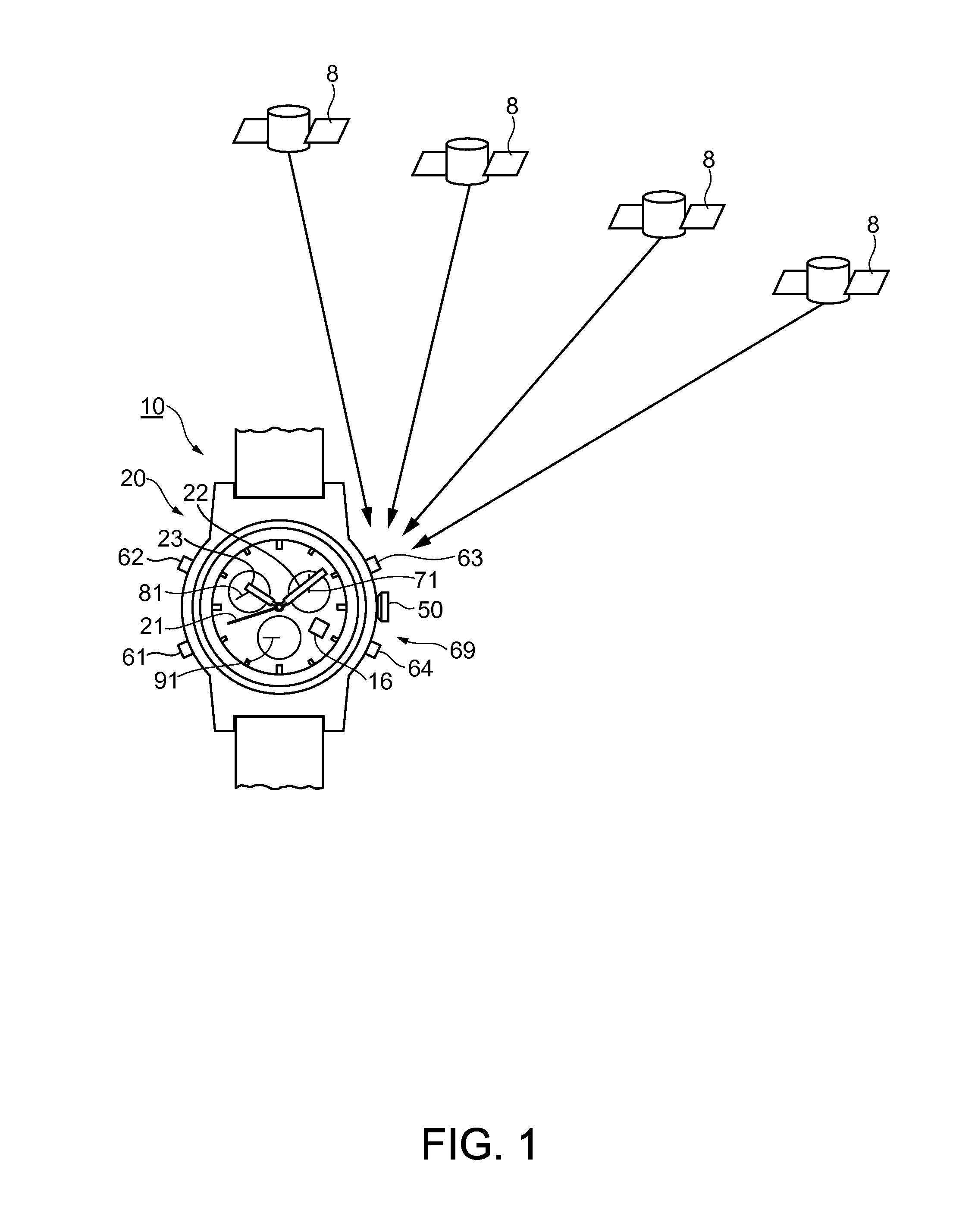
[0143]FIG. 1 is a schematic front view of an electronic timepiece 10 according to a first embodiment of the invention.

[0144]As illustrated in FIG. 1, the electronic timepiece 10 is configured to acquire time information by receiving a satellite signal from at least one GPS satellite 8 within multiple GPS satellites 8 following a predetermined orbit of the earth in space, and to calculate position information by receiving the satellite signal from at least three GPS satellites 8. The GPS satellite 8 is an example of position information satellites, and is present at multiple locations in the sky above the earth. Currently, approximately 30 GPS satellites 8 are turning around.

Schematic Configuration of Electronic Timepiece

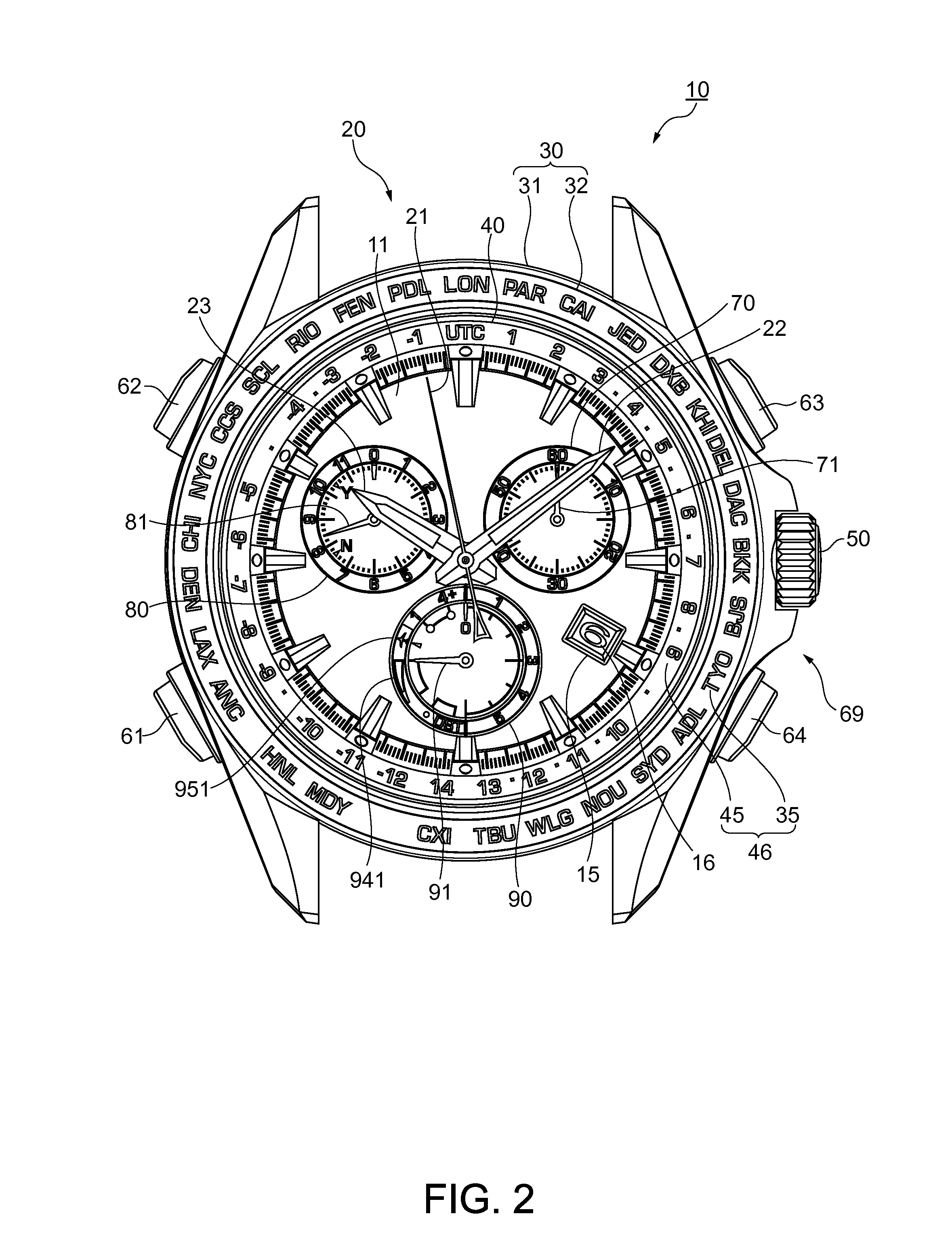
[0145]FIG. 2 is a detailed front view of the electronic timepiece 10. FIG. 3 is a schematic cross-sectional view of the electronic timepiece 10.

[0146]The electronic timepiece 10 is a wrist timepiece which a user wears on his or her wrist. The electronic timepiece 10 ...

second embodiment

[0378]FIGS. 21 to 24 illustrate a second embodiment of the invention.

[0379]An electronic timepiece 10A according to the embodiment is different from the electronic timepiece 10 according to the above-described first embodiment in that the chronograph function is not provided and the day display is provided.

[0380]However, the basic configuration other than the display device 20, the input device 69, and the control device 150 which relate to the above-described different points is the same as that in the electronic timepiece 10 according to the above-described first embodiment. The same reference numerals are given to the same configuration elements, and repeated description will be omitted.

[0381]In FIG. 22A, the electronic timepiece 10A according to the embodiment has the indicating hands 21, 22, 23, and 81, and the calendar wheel 16, as a display device 20A. The indicating hands 21, 22, and 23 respectively display the second, the minute, and the hour of the current time which are m...

third embodiment

Operation Effect in Third Embodiment

[0469]When the crown 50 is located at the zero stage position, even if the switch wheel 560 is rotated, the switch contact point spring body 570 does not come into contact with the switch wheel 560. Accordingly, a user does not feel a sense of resistance, even when the crown 50 is rotated. Therefore, the user can intuitively recognize that no input operation is performed. In addition, when the crown 50 is located at the first stage position and the second stage position, the user feels the sense of resistance by rotating the crown 50. In this manner, the user can intuitively recognize that the input operation is performed. This can improve usability.

[0470]Even if the crown 50 is rotated at the zero stage position, the switch wheel 560 does not come into contact with the switch contact point spring body 570. Accordingly, there is no possibility that components such as the switch contact point spring 580 or the return spring portion 591 of the setti...


PUM


Abstract

An electronic timepiece has a display device that displays display information, a drive mechanism that drives the display device, a crown that can perform a rotary operation, and a control device that corrects the display information displayed on the display device by the rotary operation of the crown. The control device has a single correction mode and a continuous correction mode which are selected by the rotary operation of the crown. In the single correction mode, a single correction signal is output to the drive mechanism so that the display device is corrected as much as a single correction quantity. In the continuous correction mode, a continuous correction signal is output to the drive mechanism so that the display device is corrected as much as a continuous correction quantity. The continuous correction quantity is set depending on types of the display information to be corrected in the continuous correction mode.

Description

BACKGROUND[0001]1. Technical Field[0002]The present invention relates to an electronic timepiece and a movement.[0003]2. Related Art[0004]In the related art, an electronic timepiece is known which corrects display information by using an electronic crown (for example, JP-A-2008-134129).[0005]The electronic timepiece disclosed in JP-A-2008-134129 can display the display information such as time by using a display unit such as an indicating hand on a dial, and can correct the display information by using the electronic crown.[0006]In the electronic timepiece disclosed in JP-A-2008-134129, when the display information is corrected by using an electronic crown, depending on an axially pulled-out position of the crown, a measurement condition of a rotation signal is variable when the crown is rotatably operated. Based on the measurement condition, a correction quantity of the correction-targeted information is variable.[0007]Since the correction quantity is variable in this way, a weak p...

Claims


Application Information

Patent Timeline
Patent Type & Authority Applications(United States)
IPC IPC(8): G04G9/00
CPCG04G9/00G04C9/08G04G5/00G04G5/04G04B27/02G04B3/04G04G9/0076G04R20/02
Inventor NISHIJIMA, HIROKAZUMITANI, TOSHIHIRONAKANISHI, NOBUHIKO
Owner SEIKO EPSON CORP
Why Eureka
Try Eureka