Split function valve

a valve and function technology, applied in the field of equipment control, can solve the problems of increased stress and fatigue on the wing folding linkage, increased stress, and inability to achieve simultaneous functionality

Active Publication Date: 2016-03-24
UNVERFERTH MFG
View PDF8 Cites 1 Cited by
  • Summary
  • Abstract
  • Description
  • Claims
  • Application Information

AI Technical Summary

Benefits of technology

[0009]In accordance with aspects of the invention, a method includes converting a single input flow into two output flows. The m...

Problems solved by technology

This simultaneous functionality may not always be desirable.
This results in unnecessary stress and fatigue upon the wing folding linkage as the wing fold linkage does not need to become loaded for in-field performance.
This is further shown in FIG. 1 which describes how when lowering the machine first and then unfolding the wings, the wings contact the ground prior to complete unfolding which results in additional stress.
Other issues can occur as a result of when a tillage tool is lowered prior to u...

Method used


Image

  • Split function valve
  • Split function valve
  • Split function valve

Examples


Embodiment Construction

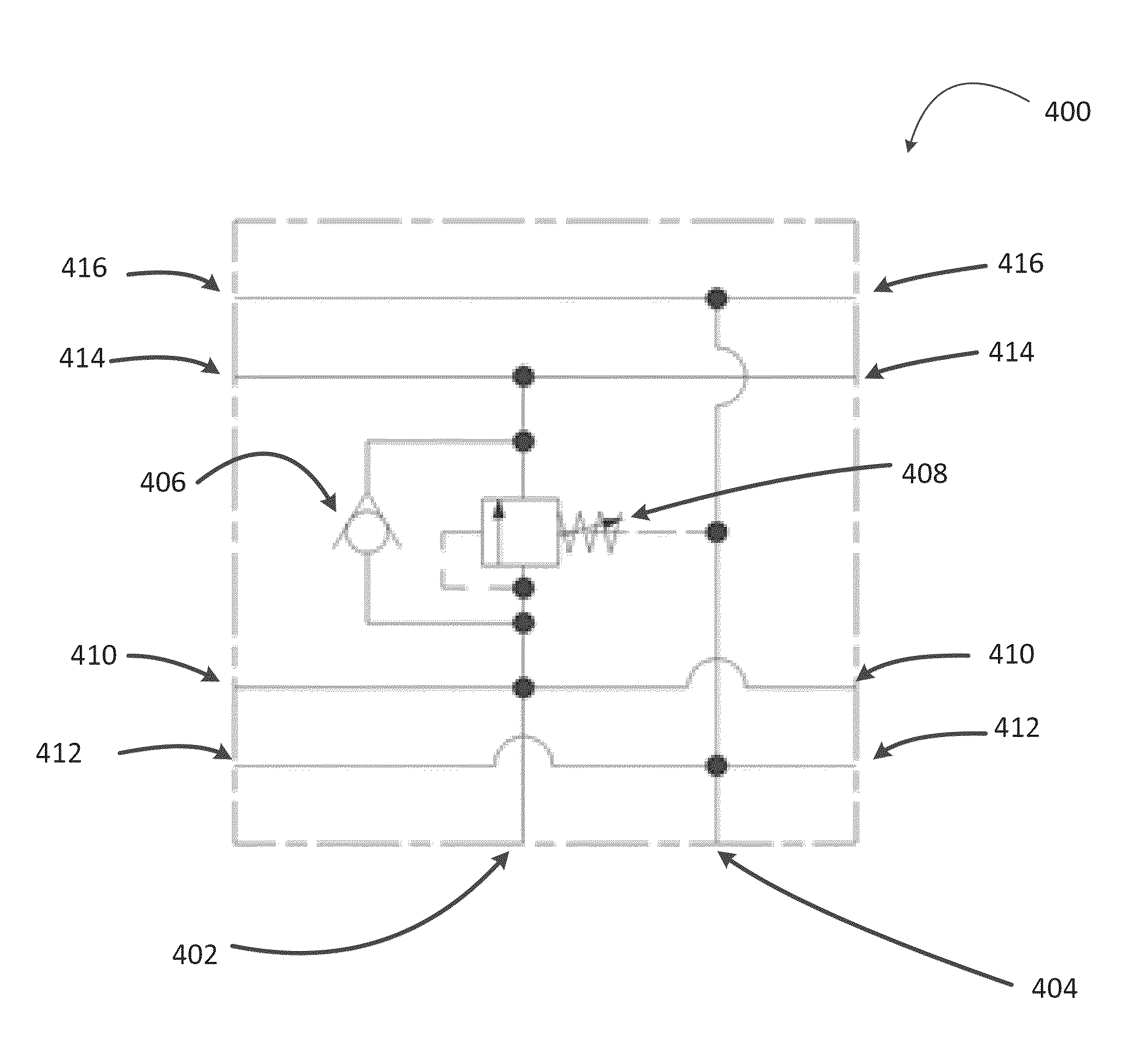
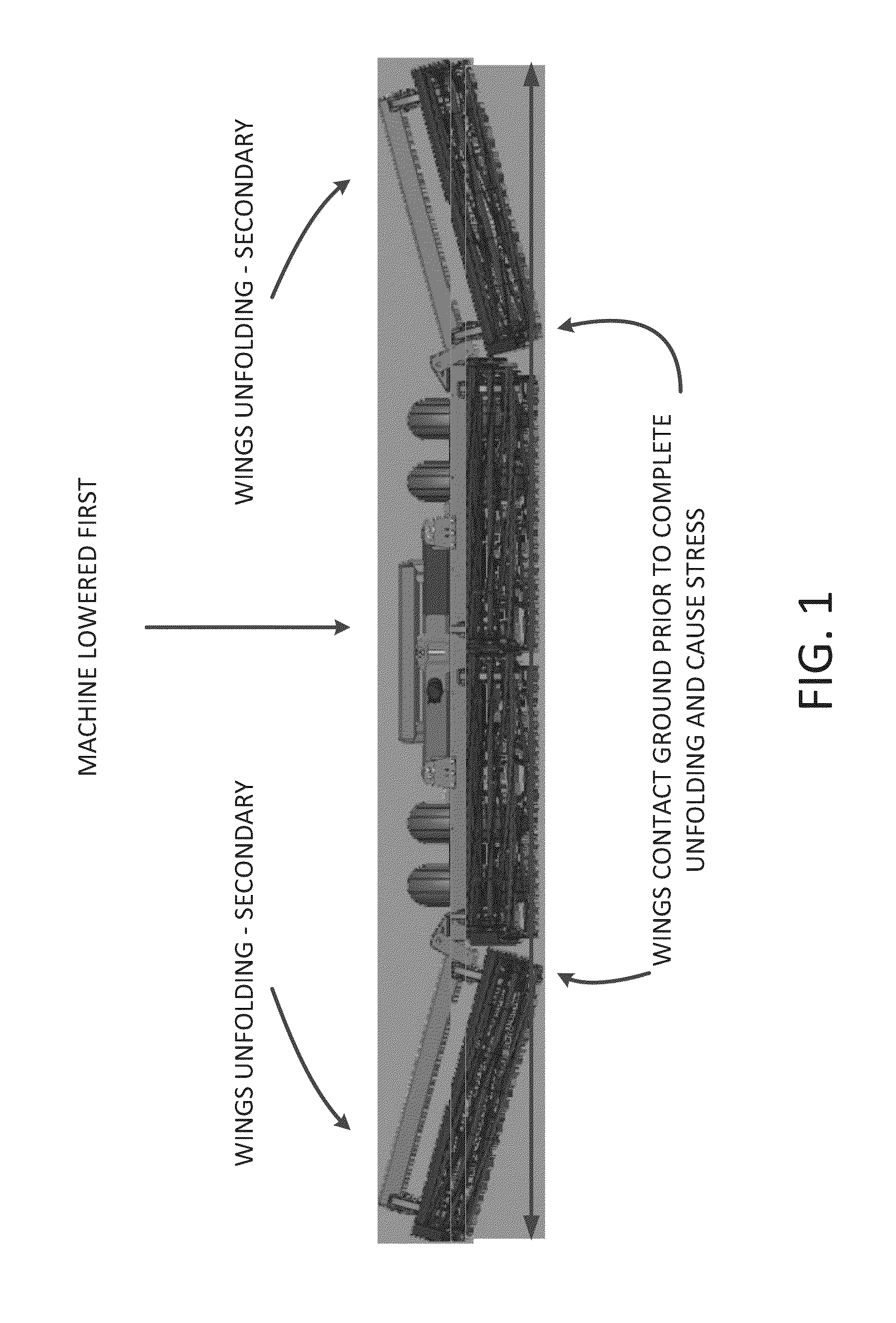
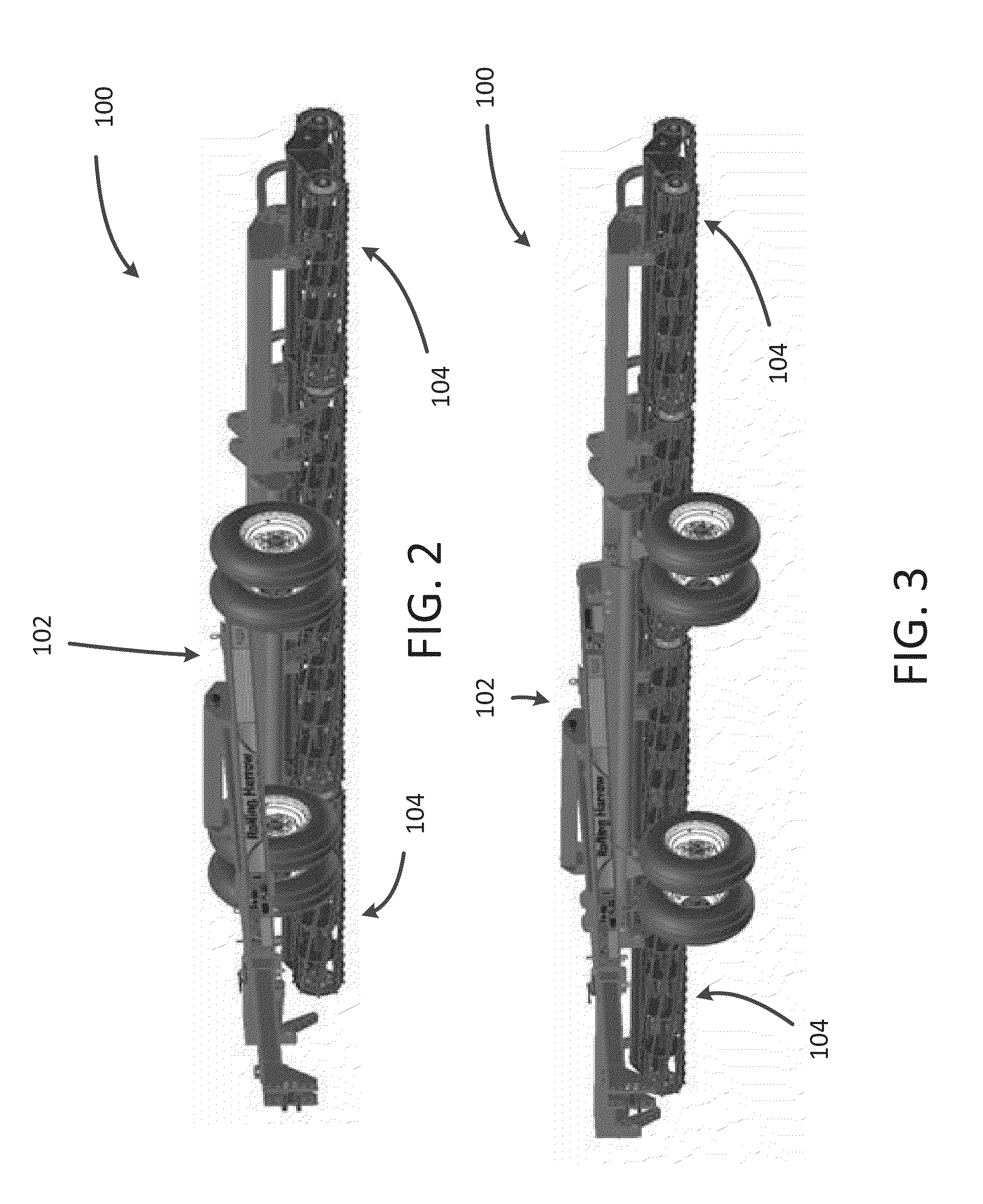
[0016]Apparatus, systems, and methods described herein may create a control system that prevents various types of machinery from performing one operation prior to the performance of another operation. As such, the present invention provides for a control system that can reduce stress and fatigue to various portions of the machinery. For example, the machinery may be tillage tools used within the agricultural industry (e.g., farming) and the control system may reduce stress and fatigue associated with the operation of the tillage tool. In embodiments, the tillage tools can include wings that are raised and lowered by the control system. The wings, for example, can be a device that, when lowered, tills the field. In embodiments, the control system may first lift the tillage tool and then fold the wings of the tillage tool. Additionally, or alternatively, the control system may unfold the wings and then lower the tillage tool.

[0017]As a result, the control system allows for (i) using a...


PUM


Abstract

A method includes converting a single input flow into two output flows. The method further includes sequencing the output flows to completely raise a machine prior to folding of wings associated with the machine

Description

BACKGROUND OF THE INVENTION[0001]1. Field of the Invention[0002]The present invention relates to the field of equipment control.[0003]2. Description of the Background Art[0004]Various types of equipment / machinery can be operated and controlled by using some kind of control mechanism. For example, the control mechanism can use a variety of different systems, such as hydraulic systems, pneumatic systems, and / or other types of systems. Furthermore, the control mechanism may include different types of valves, pumps, motors, reservoirs, and / or other components to implement the control mechanism.[0005]For example, in the agriculture industry, there are many types of tillage tools that are controlled and operated using a control mechanism. These tillage tools can be designed to be towed behind a vehicle, such as a tractor, so as to prepare a field to facilitate in the planting of crops. The control of the tillage tools may be provided, for example, by a hydraulic supply located on the vehi...

Claims


Application Information

Patent Timeline
IPC IPC(8): A01B63/00
CPCA01B63/008A01B73/044
Inventor STEFFAN, THOMASGARBERSON, JOHN
Owner UNVERFERTH MFG
Why Eureka
Try Eureka