Shielding device and refrigerator comprising same

a shielding device and refrigerator technology, applied in the field of refrigerators, can solve the problems of increased production cost of air doors, increased development cost, and large pressure loss of forced draft fans, and achieve the effects of increasing the effect of discharging moisture, increasing the thread mechanism of shielding devices, and increasing the drainage

Active Publication Date: 2016-06-02
HAIER ASIA INT CO LTD +1
View PDF20 Cites 13 Cited by
  • Summary
  • Abstract
  • Description
  • Claims
  • Application Information

AI Technical Summary

Benefits of technology

[0014]One of the objectives of the present invention is to provide a shielding device that effectively prevents hot air from flowing into a storage chamber during defrosting and a refrigerator having the shielding device, so as to solve the above-noted problems.
[0022]According to the present invention, opening and closing actions of the forced draft fan cover are achieved through a thread mechanism screwed with a drive shaft that extends to pass through the forced draft fan cover. Moreover, an air duct that allows the air flows from the inside of the forced draft fan cover to the outside is provided between the drive shaft and the forced draft fan cover. Accordingly, even if moisture intrudes between the drive shaft and the forced draft fan cover in a use condition, the moisture will be discharged to the outside via the air duct. Thus, that moisture freezes to make the thread mechanism of the shielding device incapable of operating can be prevented.
[0023]In addition, setting a side surface of the thread of the drive shaft in a tilted shape can ensure that there is a greater gap between it and the threaded slot of the forced draft fan cover. Therefore, an effect of discharging moisture is increased.
[0024]Further, cutting a notch from one part of the forced draft fan cover ensures the air duct. Thus, a drainage effect is also increased.
[0025]Moreover, the forced draft fan cover of the present invention can move in a manner of leaving a cooling chamber, and thus flow loss of cooling air is very small. Therefore, air that has greater flow velocity in a turning radius direction of the air outside of the forced draft fan can flow into a cooling air duct through the open portion with smaller flow resistance. Therefore, pressure loss of cooling air circulating in the refrigerator can be reduced, and cooling efficiency can be increased.

Problems solved by technology

In a conventional refrigerator, when a cooler is defrosted, there is a problem that hot air surrounding the cooler heated by a defrost heater flows into a storage chamber to raise the temperature in the storage chamber.
Therefore, if air doors adapted to various models of air ducts are disposed, the kinds of the air doors will increase, to become a multi-specification & small batch production manner, and there is a problem that development cost and production cost of the air doors increase.
In addition, when the wind ring shield 301 shown in FIG. 10B is used at the air outside of the forced draft fan, there is a problem that an air-out portion of the forced draft fan has great pressure loss.
Therefore, a heretofore unaddressed need exists in the art to address the aforementioned deficiencies and inadequacies.

Method used


Image

  • Shielding device and refrigerator comprising same
  • Shielding device and refrigerator comprising same
  • Shielding device and refrigerator comprising same

Examples


first embodiment

Structure of a Shielding Device

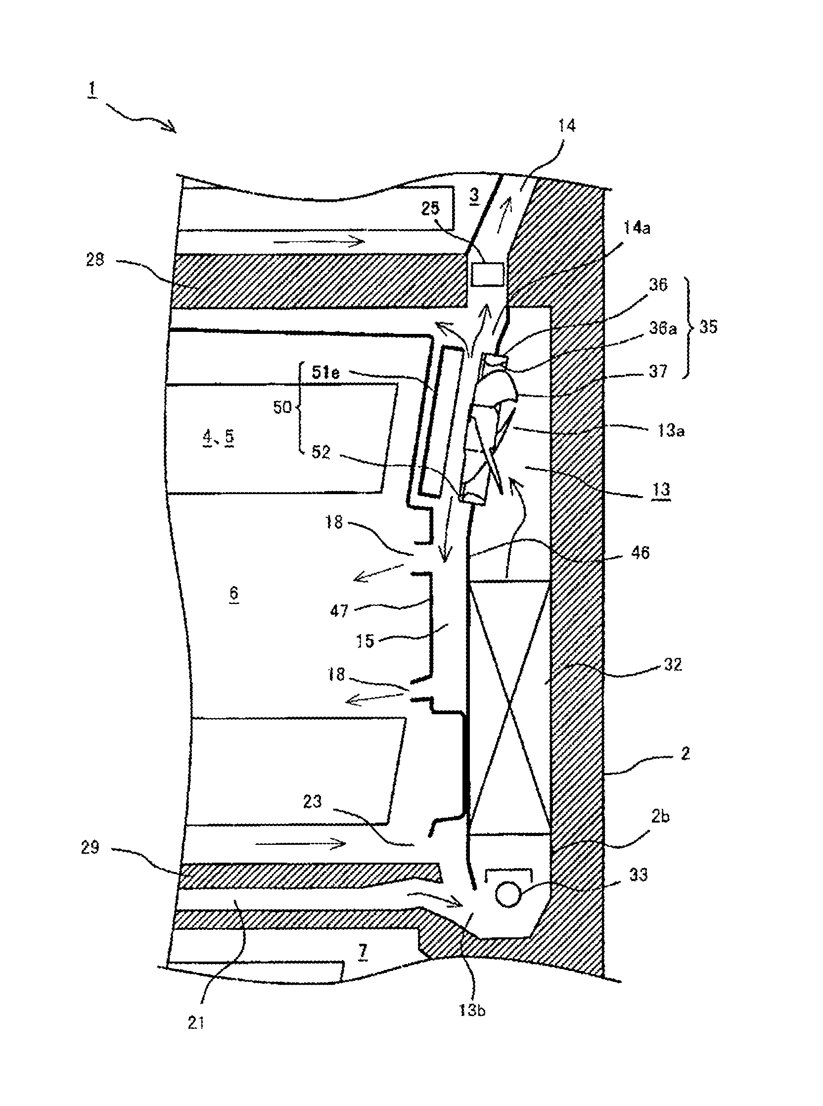
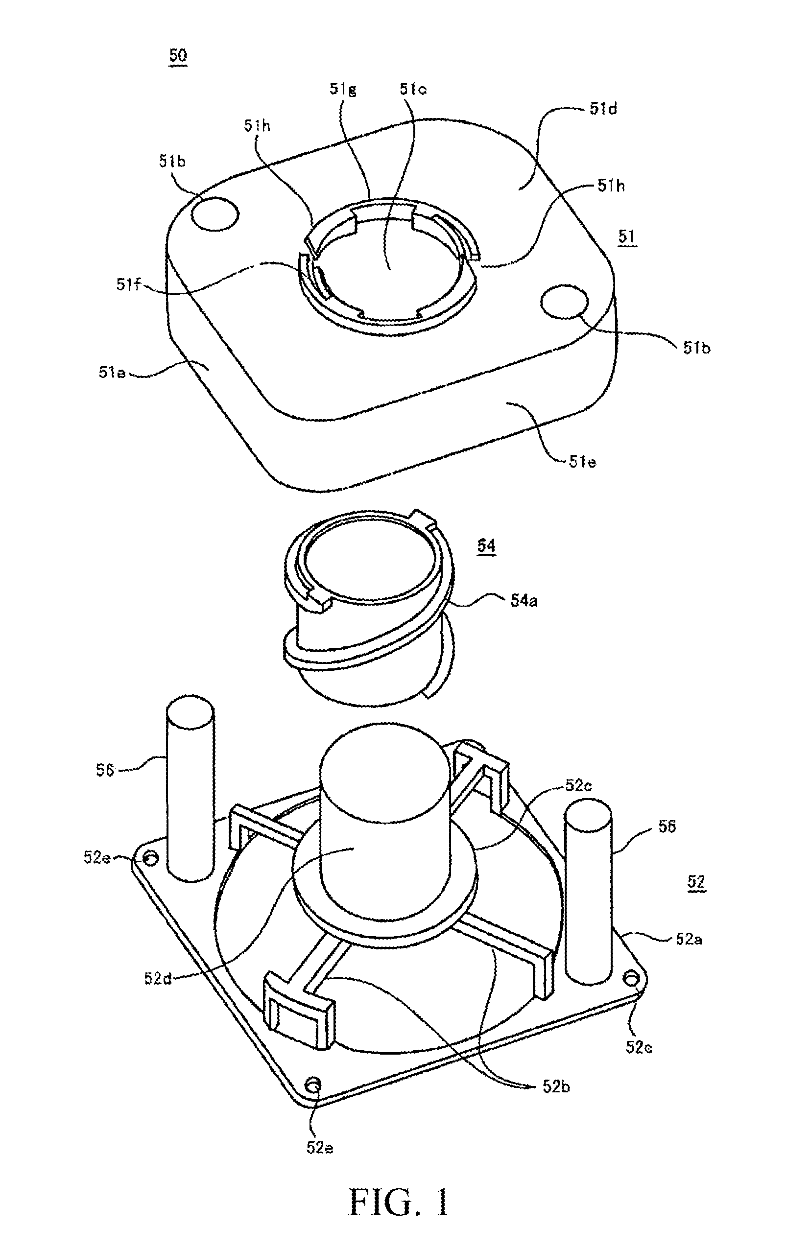
[0047]FIGS. 1, 2A-2C and 3A-3D show the structure of a shielding device 50 according to this exemplary embodiment of the present invention. FIG. 1 is a perspective view indicating that components of the shielding device 50 are decomposed along a longitudinal direction. FIGS. 2A-22C are diagrams of parts of the shielding device 50. FIGS. 3A-3D are diagrams of functions of the shielding device 50.

[0048]Referring to FIG. 1, the shielding device 50 mainly includes a forced draft fan cover 51 substantially cover-shaped, a drive shaft 54 which extends to pass through and drives the forced draft fan cover 51, and a support base 52 used for supporting the forced draft fan cover 51 and the drive shaft 54. Referring to FIG. 7, the main function of the shielding device 50 is inhibiting hot air from leaking to a refrigerating chamber supply air duct 14 during defrosting by closing an open portion of a cooling chamber 13 in a defrosting step.

[0049]In certain embodi...

second embodiment

Structure of a Refrigerator

[0070]Referring to FIG. 4, a forward external view of a schematic structure of a refrigerator 1 is shown according to one embodiment of the present invention. As shown in FIG. 4, the refrigerator 1 of this embodiment has a heat-insulating cabinet 2 as a body, and a storage chamber that stores food and the like is formed inside the heat-insulating cabinet 2. The inside of the storage chamber is partitioned into multiple receiving chambers 3-7 according to different storage temperatures and uses. The uppermost layer of the storage chamber is a refrigerating chamber 3. An ice-making chamber 4 is on a lower left side of the refrigerating chamber 3, while an upper freezing chamber 5 is on a lower right side of the refrigerating chamber 3. A lower layer of the ice-making chamber 4 and the upper freezing chamber 5 is a lower freezing chamber 6. The lowest layer of the storage chamber is a vegetable chamber 7. Besides, the ice-making chamber 4, the upper freezing ...

third embodiment

Working Process of the Refrigerator

[0106]In the following, the working process of the refrigerator 1 having the above structure is described with reference to the figures mentioned above.

[0107]First, the operation of cooling the refrigerating chamber 3 is described. As shown in FIG. 5, the compressor 31 operates, the refrigerating chamber air door 25 is opened, to make the forced draft fan 35 operate, and thus the refrigerating chamber 3 is cooled. That is, air cooled by the cooler 32 sequentially passes through the air supply outlet 13a (forced draft fan 35) of the cooling chamber 13, the refrigerating chamber air door 25, the refrigerating chamber supply air duct 14 and the blowout port 17, to be supplied to the refrigerating chamber 3. Accordingly, food and the like stored in the refrigerating chamber 3 can be cooled and stored at an appropriate temperature.

[0108]At this point, referring to FIG. 7, the shielding device 50 becomes an open state, and the cooling chamber 13 and the ...


PUM


Abstract

The disclosure relates to a shielding device for closing a path through which air circulates in a refrigerator and a refrigerator having shielding device. The shielding device includes a forced draft fan cover having a threaded hole formed with a threaded slot; and a drive shaft formed with a thread being screwed with the threaded slot and extended to pass through the threaded hole, where an air duct that allows the air flows from the inside of the forced draft fan cover to the outside is provided between the drive shaft and the forced draft fan cover.

Description

CROSS-REFERENCE TO RELATED APPLICATIONS[0001]This application is a continuation application of International Patent Application No. PCT / CN2014 / 086859, filed Sep. 18, 2014, which itself claims priority to and benefit of Japanese Patent Application No. 2013-197002, filed Sep. 24, 2013, which are hereby incorporated herein in their entireties by reference.FIELD OF THE INVENTION[0002]The present invention relates generally to a refrigerator, and more particularly, to a shielding device that blocks an air duct where cool air circulates in a refrigerator according to needs and a refrigerator having the shielding device.BACKGROUND OF THE INVENTION[0003]The background description provided herein is for the purpose of generally presenting the context of the present invention. The subject matter discussed in the background of the invention section should not be assumed to be prior art merely as a result of its mention in the background of the invention section. Similarly, a problem mentioned ...

Claims


Application Information

Patent Timeline
Patent Type & Authority Applications(United States)
IPC IPC(8): F25D17/04F25D17/08F25D17/06F25D21/06
CPCF25D17/045F25D21/06F25D17/067F25D17/065F25D17/08F25D2317/0681
Inventor OYU, HIDEKIKURATANI, TOSHIHARUTATENO, TAKAYAYAMAGUCHI, TATSUHIKO
Owner HAIER ASIA INT CO LTD
Why Eureka
Try Eureka