Headrest support structure

Active Publication Date: 2016-06-16
TOYOTA JIDOSHA KK +1
View PDF18 Cites 14 Cited by
  • Summary
  • Abstract
  • Description
  • Claims
  • Application Information

AI Technical Summary

Benefits of technology

[0009]The invention thus provides a headrest support structure capable o

Problems solved by technology

However, if the fit of these headrest supports 54 is tight, assembly of the headrest supports 54 into the brackets 51 may be difficult.
Also, even if the headrest is not used as a dynamic damper, when the headrest is pivotally supported on the seat back, a similar problem may occur.
That is, if the position of the pivot center of the

Method used


Image

  • Headrest support structure
  • Headrest support structure
  • Headrest support structure

Examples


Example

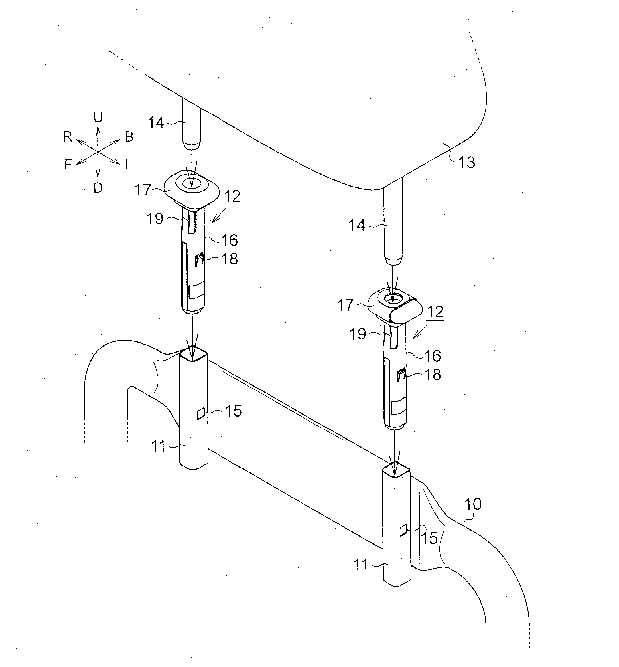
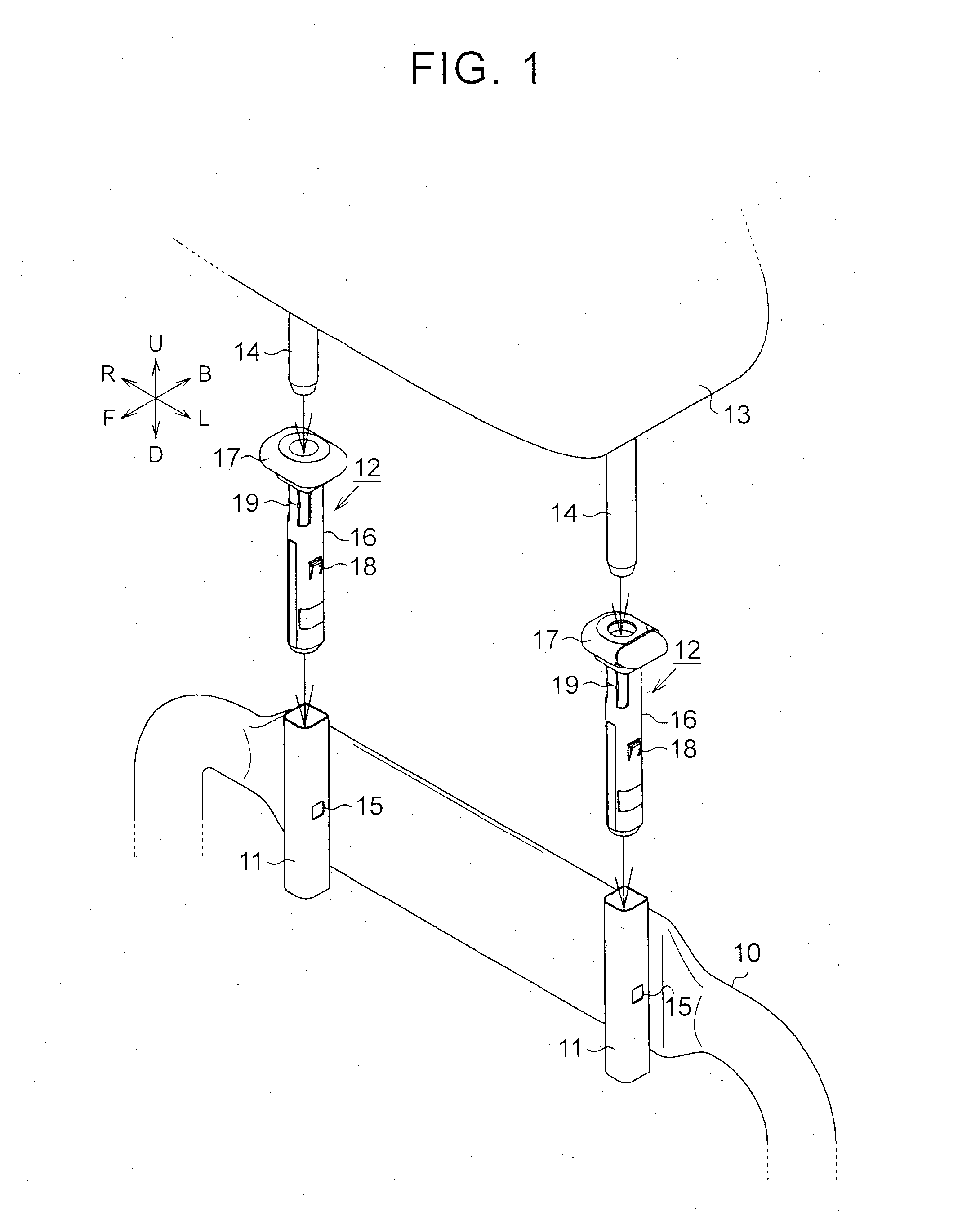
[0031]Hereinafter, a first example embodiment of the headrest support structure of the invention will be described in detail with reference to FIGS. 1 to 6. In the description below, a direction corresponding to forward of an occupant seated in a seat will be referred to as “seat front F”, a direction corresponding to rearward of the occupant will be referred to as “seat rear B”, a direction corresponding to the left of the occupant will be referred to as “seat left L”, and a direction corresponding to the right of the occupant will be referred to as “seat right R”. Also, a direction to a side where the headrest is positioned when viewed from the seat back will be referred to as “seat upper U” or “above U in the vertical direction of the seat”, and a direction opposite this direction will be referred to as “seat lower D” or “below D in the vertical direction of the seat”.

[0032]As shown in FIG. 1, the headrest support structure of this example embodiment includes two brackets 11 that...


PUM


Abstract

A headrest support having a hollow cylindrical shape and into which a headrest stay is inserted, is inserted into a bracket that has a hollow cylindrical shape and is fixed to a seat back frame. A protrusion, a tip end of which is a pivot center of the headrest support, formed such that a protrusion amount thereof increases in response to insertion of the headrest stay, is provided on an outer peripheral surface of this headrest support.

Description

BACKGROUND OF THE INVENTION[0001]1. Field of the Invention[0002]The invention relates to a headrest support structure that pivotally supports a headrest.[0003]2. Description of Related Art[0004]One known headrest support structure makes a headrest serve as a dynamic damper by pivotally elastically-supporting the headrest on a seat back. The support structure described in Japanese Utility Model Application Publication No. 61-149552 (JP 61-149552 U), for example, is one such headrest support structure.[0005]FIG. 7 is a view of the structure of a headrest support structure described in JP 61-149552 U. This headrest support structure has a bracket 51 that is fixed to a seat back frame 50 that is a frame member of a seat back. The bracket 51 is formed by a metal plate member that is bent in a general sideways U-shape. Through-holes 52 and 53 are formed in an upper portion and a lower portion, respectively, of this bracket 51. Headrest supports 54 that are made of resin and support headre...

Claims


Application Information

Patent Timeline
IPC IPC(8): A47C7/38
CPCA47C7/383B60N2205/20B60N2/812B60N2/80B60N2/809B60N2/897B60N2/894B60N2/826B60N2/832B60N2/68A47C7/36B60N2/7094B60N2/686B60N2/72B60N2/682
Inventor TAKAHASHI, GENOZAKI, AKIHIDE
Owner TOYOTA JIDOSHA KK
Why Eureka
Try Eureka