
Headrest support structure

a support structure and headrest technology, applied in the direction of seat frames, chairs, transportation and packaging, etc., can solve the problems of difficult assembly of the headrest supports into the brackets b>51/b>, inability to pivot as intended, similar problems, etc., to achieve the effect of ensuring the accuracy of the pivot operation of the headres

Active Publication Date: 2017-10-10
TOYOTA JIDOSHA KK +1
View PDF26 Cites 1 Cited by
  • Summary
  • Abstract
  • Description
  • Claims
  • Application Information

AI Technical Summary

Benefits of technology

The invention is a headrest support structure that ensures the accurate pivot operation of a headrest. It includes a protrusion on the outer surface of the headrest support that acts as a pivot center. When the headrest stay is not inserted, the protrusion is pushed out, allowing for smoother insertion. The structure also includes two slits in the headrest support to further reduce the force required for deformation and enable smooth insertion of the headrest stay. Additionally, the position of the tip end of the protrusion is designed to minimize interference between the protrusion and the inner surface of the bracket when the headrest support is inserted. Overall, the invention provides an effective and easy way to ensure the proper pivot operation of a headrest.

Problems solved by technology

However, if the fit of these headrest supports 54 is tight, assembly of the headrest supports 54 into the brackets 51 may be difficult.
Also, even if the headrest is not used as a dynamic damper, when the headrest is pivotally supported on the seat back, a similar problem may occur.
That is, if the position of the pivot center of the headrest ends up being offset due to assembly tolerance of the members, the headrest will be unable to pivot as intended.
On the other hand, in order to inhibit the position of the pivot center of the headrest from being offset, the fit of the members needs to be tight, but if the fit is tight, assembly of the part may be difficult.

Method used


Image

  • Headrest support structure
  • Headrest support structure
  • Headrest support structure

Examples


Embodiment Construction

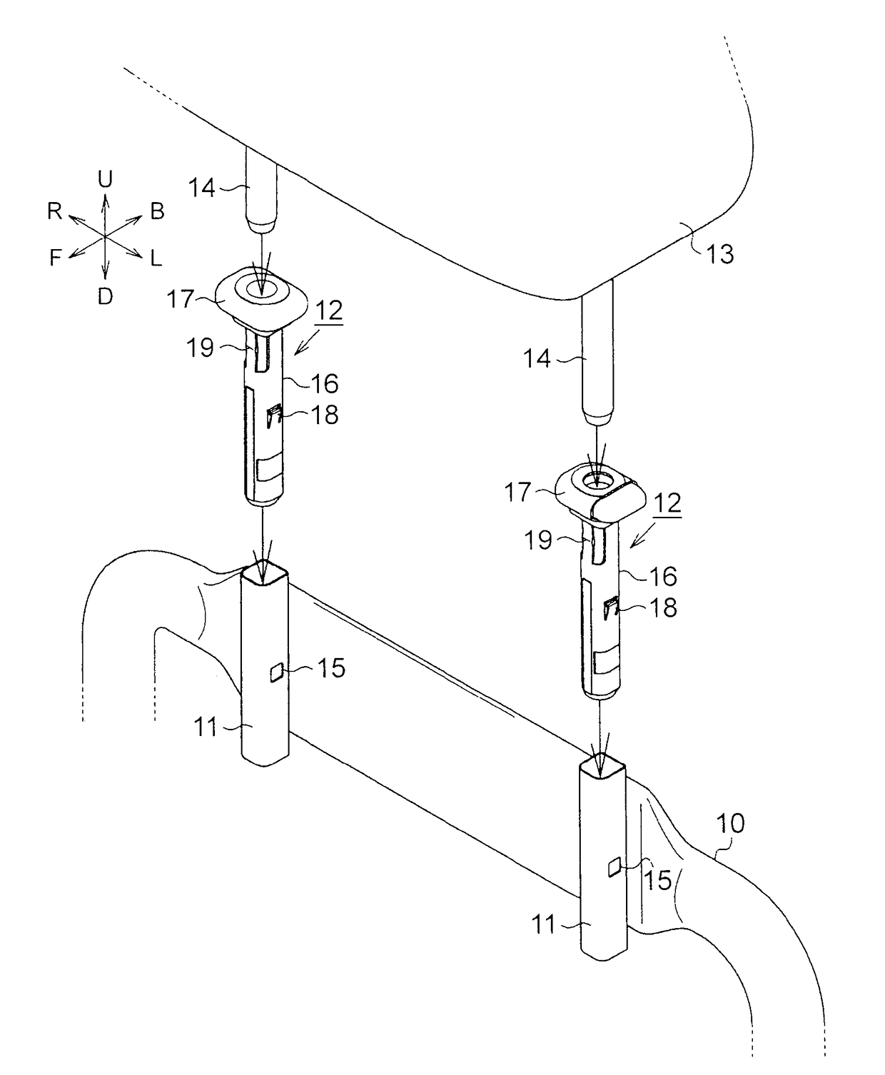
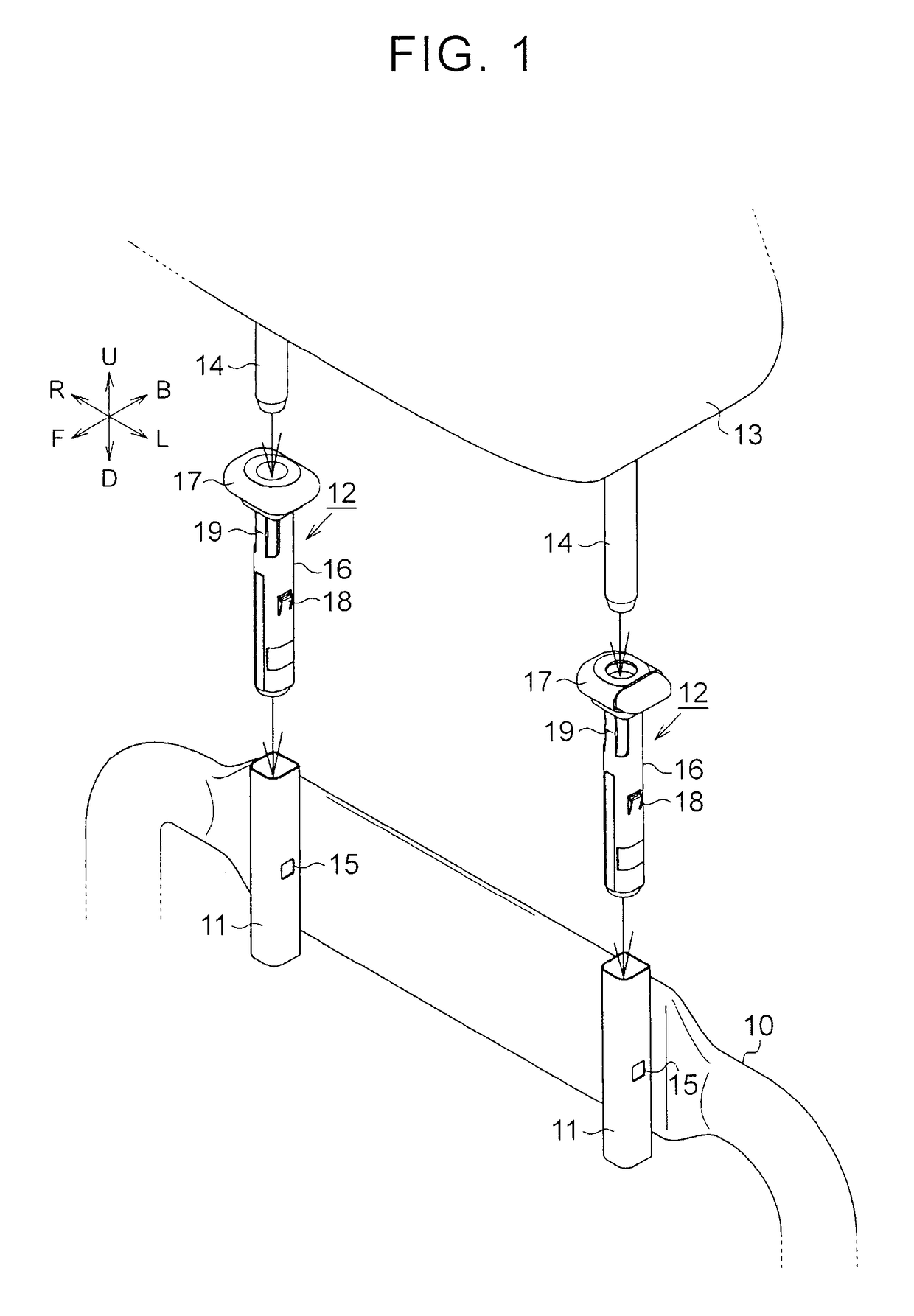
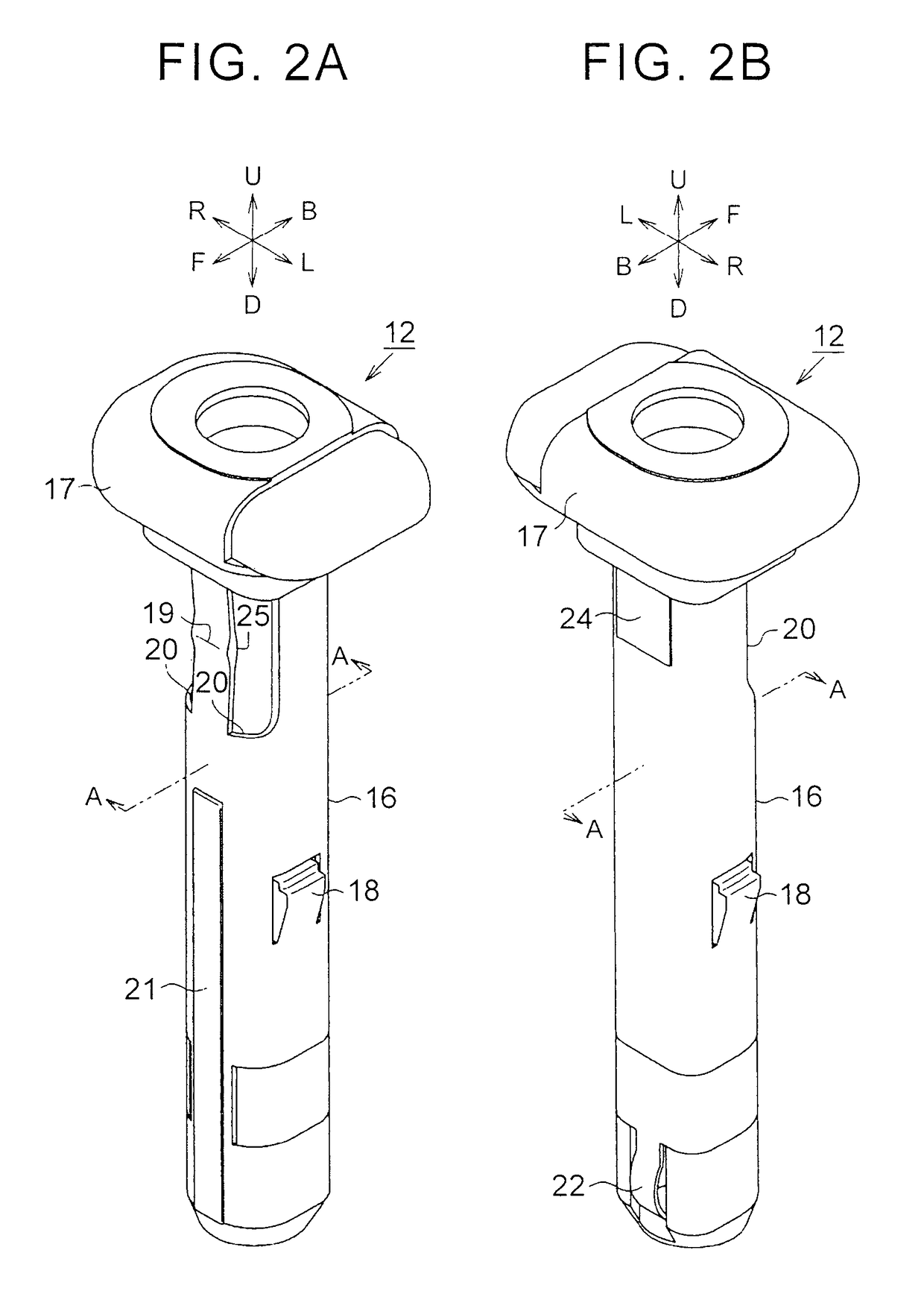
[0032]Hereinafter, a first example embodiment of the headrest support structure of the invention will be described in detail with reference to FIGS. 1 to 6. In the description below, a direction corresponding to forward of an occupant seated in a seat will be referred to as “seat front F”, a direction corresponding to rearward of the occupant will be referred to as “seat rear B”, a direction corresponding to the left of the occupant will be referred to as “seat left L”, and a direction corresponding to the right of the occupant will be referred to as “seat right R”. Also, a direction to a side where the headrest is positioned when viewed from the seat back will be referred to as “seat upper U” or “above U in the vertical direction of the seat”, and a direction opposite this direction will be referred to as “seat lower D” or “below D in the vertical direction of the seat”.

[0033]As shown in FIG. 1, the headrest support structure of this example embodiment includes two brackets 11 that...


PUM


Abstract

A headrest support having a hollow cylindrical shape and into which a headrest stay is inserted, is inserted into a bracket that has a hollow cylindrical shape and is fixed to a seat back frame. A protrusion, a tip end of which is a pivot center of the headrest support, formed such that a protrusion amount thereof increases in response to insertion of the headrest stay, is provided on an outer peripheral surface of this headrest support.

Description

CROSS-REFERENCE TO RELATED APPLICATIONS[0001]This is a national phase application based on the PCT International Patent Application No. PCT / IB2014 / 001311 filed Jul. 11, 2014, claiming priority to Japanese Patent Application No. 2013-150656 filed Jul. 19, 2013, the entire contents of both of which are incorporated herein by reference.BACKGROUND OF THE INVENTION[0002]1. Field of the Invention[0003]The invention relates to a headrest support structure that pivotally supports a headrest.[0004]2. Description of Related Art[0005]One known headrest support structure makes a headrest serve as a dynamic damper by pivotally elastically-supporting the headrest on a seat back. The support structure described in Japanese Utility Model Application Publication No. 61-149552 (JP 61-149552 U), for example, is one such headrest support structure.[0006]FIG. 7 is a view of the structure of a headrest support structure described in JP 61-149552 U. This headrest support structure has a bracket 51 that is...

Claims


Application Information

Patent Timeline
Patent Type & Authority Patents(United States)
IPC IPC(8): A47C1/10A47C7/38A61G15/00A47C7/36B60R22/28B60N2/48B60N2/68B60N2/70B60N2/72
CPCA47C7/383B60N2/4808B60N2205/20A47C7/36B60N2/48B60N2/4811B60N2/4826B60N2/4832B60N2/68B60N2/682B60N2/686B60N2/7094B60N2/72B60N2002/4894B60N2002/4897B60N2/812B60N2/80B60N2/809B60N2/897B60N2/894B60N2/826B60N2/832
Inventor TAKAHASHI, GENOZAKI, AKIHIDE
Owner TOYOTA JIDOSHA KK
Learn More