Linking transconnector for coupling spinal rods

a transconnector and spinal rod technology, applied in the field of spinal rod fixation devices, can solve the problems of soft tissue trauma, difficulty in providing surgeons with one or more difficulties, and rarely so geometrically aligned

Active Publication Date: 2005-04-14
SYNTHES USA
View PDF93 Cites 98 Cited by
  • Summary
  • Abstract
  • Description
  • Claims
  • Application Information

AI Technical Summary

Benefits of technology

[0008] The present invention relates to a Linking Transconnector used for coupling a first longitudinal spinal rod to a second longitudinal spinal rod. The Linking Transconnector generally includes a pair of hook engaging members for engaging the longitudinal spinal rods, a lateral rod for spanning a distance between the hook engaging members, and a locking element which interconnects the hook engaging members with the lateral rod. The locking element generally includes a locking sleeve and a bushing, the locking sleeve being slidably located on the lateral rod thereby permitting the Linking Transconnector to accommodate varying distances between the longitudinal spinal rods, while the bushing is sized and dimensioned to be disposed between the locking sleeve and the hook engaging members thereby permitting universal adjustment between the hook engaging members and the lateral rod, and thus between the longitudinal spinal rods and the lateral rod.

Problems solved by technology

The use of transconnectors, however, can provide surgeons with one or more difficulties.
However, due to a wide variety of factors, the two rods are rarely so geometrically aligned in clinical situations.
The addition of such adjustability, however, may require the transconnector to consist of numerous pieces that can be difficult to assemble and use while in the surgical environment.
Furthermore, when transconnectors are placed over adjacent spinal rods, the extended profile of the device often results in soft tissue trauma and may result in surgical complications.

Method used


Image

  • Linking transconnector for coupling spinal rods
  • Linking transconnector for coupling spinal rods
  • Linking transconnector for coupling spinal rods

Examples


Embodiment Construction

[0026] For the purposes of promoting an understanding of the principles of the invention, reference will now be made to an exemplary, non-limiting embodiment illustrated in the figures and specific language will be used to describe the same. It will nevertheless be understood that no limitation of the scope of the invention is hereby intended, such alterations and further modifications, and such further applications of the principles of the invention as illustrated herein being contemplated as would normally occur to one skilled in the art to which the invention relates.

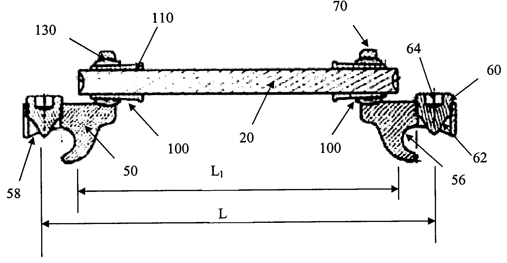
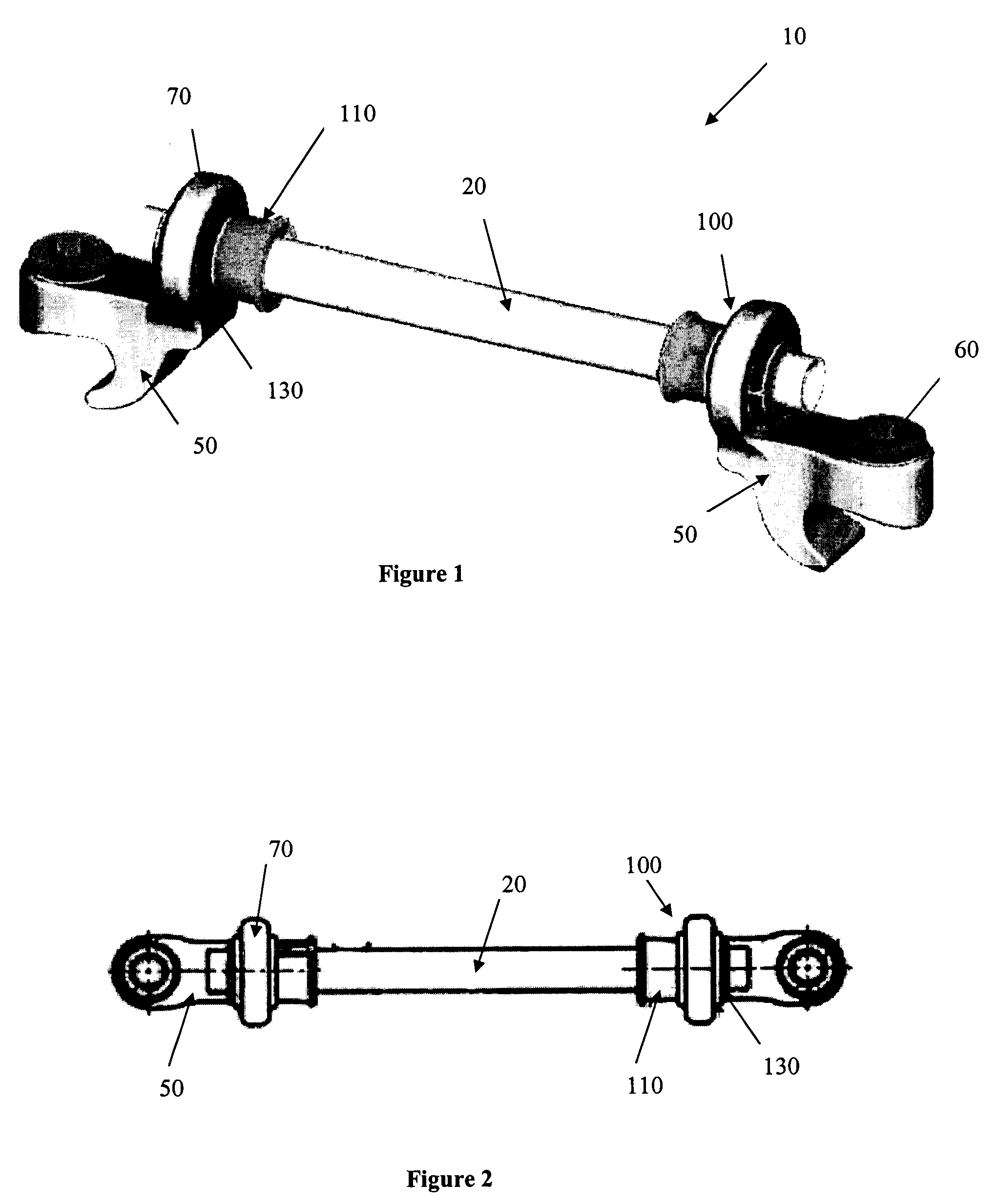
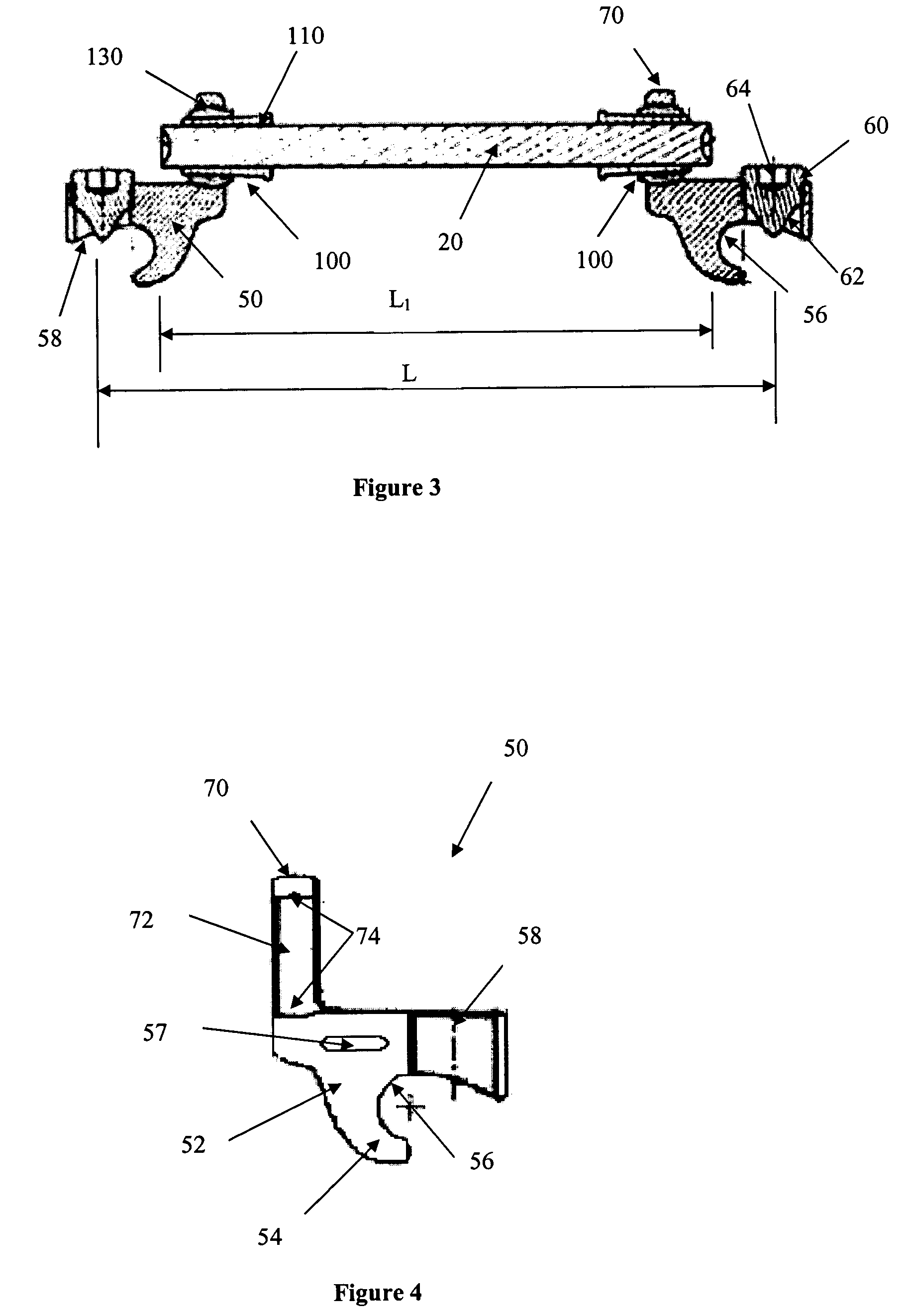
[0027] The Linking Transconnector 10 may be used for coupling a first longitudinal spinal rod to a second longitudinal spinal rod. The first and second longitudinal spinal rods may be cylindrical rods, rectangular bars, plates, or any other device appropriate for use in connecting two or more adjacent vertebral bodies to facilitate spinal fixation. For the sake of simplicity, the term “rod” will be used herein to re...


PUM


Abstract

A Linking Transconnector is disclosed for coupling a first longitudinal spinal rod to a second longitudinal spinal rod. The Linking Transconnector generally includes a pair of hook engaging members for engaging the longitudinal spinal rods, a lateral rod for spanning a distance between the hook engaging members, and a locking element which interconnects the hook engaging members with the lateral rod. The locking element being configured to allow for multiple degrees of adjustment to permit the Linking Transconnector to accommodate for varying spinal rod alignments. The locking element also permits the location of the lateral rod to be fixed relative to the hook engaging members once the desired position of the lateral rod with respect to the longitudinal spinal rods has been achieved. The locking element may also be able to fix the position of the lateral rod with respect to the hook engaging members by a force applied to the locking element.

Description

FIELD OF THE INVENTION [0001] The present invention relates to a device for spinal fixation, and in particular to a transconnector for coupling adjacent spinal rods, or other elongated members. BACKGROUND OF THE INVENTION [0002] It is often necessary to surgically correct and stabilize spinal curvatures, or to facilitate spinal fusion, for example as the result of a degenerative spinal disorder such as scoliosis. Numerous systems for use in spinal correction and fixation have been disclosed. These systems usually include a pair of elongated members, typically either rods or plates, longitudinally placed on the posterior spine on either side of spinous processes of the vertebral column. For the sake of simplicity, the term “rod” will be used hereafter to refer to any elongated member regardless of size and / or shape. Each rod is attached to various vertebra along the length of the spine by way of attachment devices which may include, but are not limited to, pedicle screws, plates, tra...

Claims


Application Information

Patent Timeline
Patent Type & Authority Applications(United States)
IPC IPC(8): A61B17/70
CPCY10T403/32032A61B17/7049A61B17/70A61B17/82A61B17/58
Inventor RYAN, CHRISTOPHER J.KEYER, THOMAS R.WALTHER, MARTIN
Owner SYNTHES USA
Why Eureka
Try Eureka