Portable Mountable Upper-Body Exercise Device

a portable, exercise device technology, applied in the direction of gymnastic exercise, therapy exercise, frictional force resistors, etc., can solve the problems of inability to remove or remount the device, the device becomes cumbersome and gets in the way, and the prior art device is less desirabl

Inactive Publication Date: 2010-03-04
GOLDBERG ELLIOTT
View PDF20 Cites 12 Cited by
  • Summary
  • Abstract
  • Description
  • Claims
  • Application Information

AI Technical Summary

Benefits of technology

[0015]In another embodiment of the invention is provided an exercise apparatus including a housing. The housing includes first and second opposed parts, each part having an inner face and an exterior. The exercise apparatus also includes a clamp, coupled to the housing, that removably attaches the exterior of the first part of the housing to a member, and a plate, disposed between the inner faces of the first and second opposed parts, and mounted for rotation about a rotation axis relative to the first and second parts. The exercise apparatus also includes a handle bar, coupled to the plate, that causes the plate to rotate relative to the housing, and a screw, mounted so as to have a longitudinal axis coinciding with the rotational axis, and engaging with a threaded receptacle, for adjustably compressing the inner faces against the plate so as to permit adjustment of resistance offered by the plate against motion relative to the housing, such that a user desirous of exercise can grasp the handle bar and cause the plate to move relative to the housing by applying to the handle bar an amount of force corresponding to the adjustment.

Problems solved by technology

Such devices tend to become cumbersome and get in the way, however, when the user does not wish to perform an upper-body workout, and it is desirable to be able to remove the portion of the apparatus used solely for exercising the upper-body and reattach it at a later time.
In these situations, devices of the prior art are less desirable, because they do not tend to allow for optimum ease of removal and remounting of the exercise device in a new location.
Removal or remounting may be impractical for the average user, or at best will require too much time and effort or may require special tools.
In some cases, such as the exercise device for use with a stroller shown in U.S. Pat. No. 5,674,165, removal and remounting may even require partial disassembly and reassembly of the resistance mechanism, meaning that the user's carefully calibrated resistance settings will be lost.

Method used


Image

  • Portable Mountable Upper-Body Exercise Device
  • Portable Mountable Upper-Body Exercise Device
  • Portable Mountable Upper-Body Exercise Device

Examples


Embodiment Construction

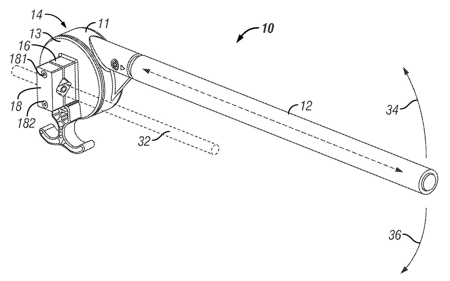
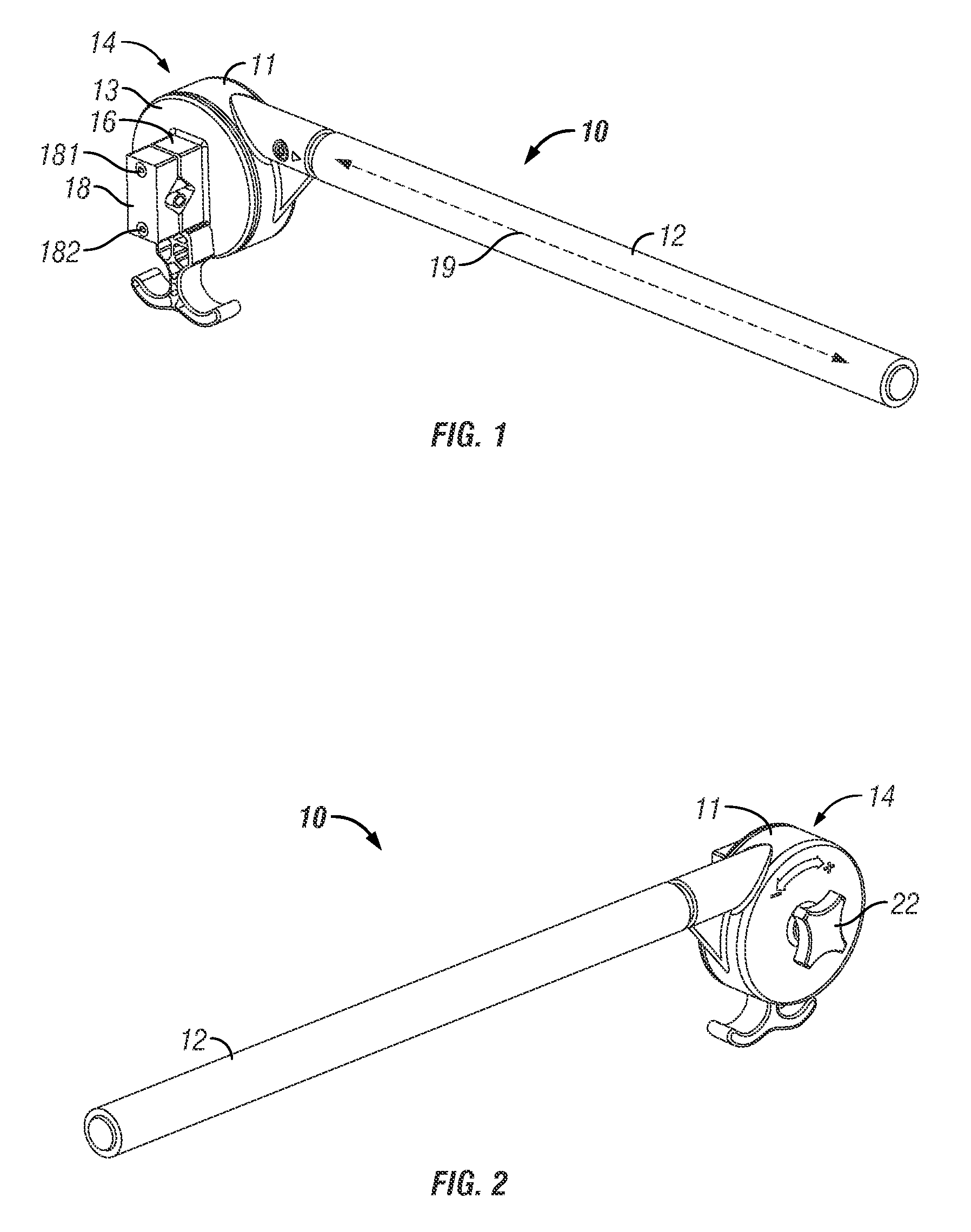
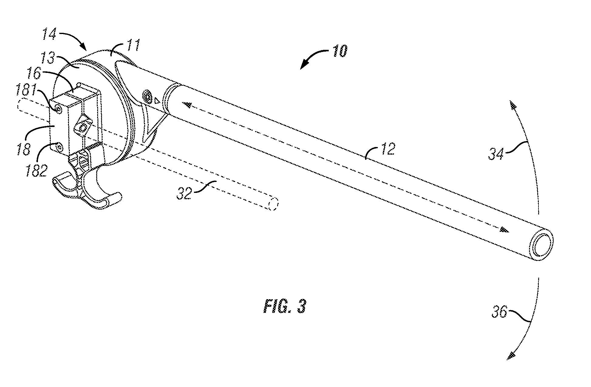
[0047]FIGS. 1 and 2 are perspective views of an exercise device 10 according to an embodiment of the present invention, in which a housing 14 is shown as viewed from the side of the first portion and the side of the second portion respectively. In the embodiment shown in FIGS. 1 and 2, the portions of the housing include a fixed portion 13 and a moveable portion 11.

[0048]Housing 14 is connected to a handle bar 12. Handle bar 12 is shown as being straight, elongated along a longitudinal axis 19. In an alternate embodiment, illustrated in FIG. 9 and discussed below, handle bar 12 also may be curved, such that it has an end portion 91 that is axially divergent from the longitudinal axis. Optionally, the handle bar is removably engagable with the housing. The handle bar may be rendered removably engagable by a variety of methods known in the art. In one embodiment, the bar may be held in place by a conventional clamp. In another embodiment, the bar may be engaged by threading the end th...


PUM


Abstract

An exercise apparatus includes a handle bar and a resistance assembly, coupled to the handle bar. The resistance assembly includes a housing having first and second opposed parts, and permitting movement of the handle bar about a rotational axis upon applying force to the handle bar. A resistance mechanism resists movement of the handle bar about the rotational axis. A screw, mounted lengthwise along the rotational axis, and engaging a threaded receptacle, adjustably compresses the spacing between the housing parts and modifies resistance to movement of the handle bar. One of the screw and the receptacle is coupled to an adjustment knob setting a user-defined resistance. A clamp, coupled to the housing, removably attaches the exterior of the first housing part to a member. A user grasps the handle bar and moves it by applying force corresponding to the resistance setting. The clamp can be utilized without operating the knob.

Description

[0001]The present application claims priority from U.S. Provisional Applications Nos. 61 / 190,160, filed Aug. 26, 2008, and 61 / 175,722, filed May 5, 2009, the full disclosures of which are hereby incorporated by reference herein.TECHNICAL FIELD[0002]The present invention relates to exercise devices, and more particularly to upper-body exercise devices capable of being mounted in a variety of locations.BACKGROUND ART[0003]It is known in the prior art to provide an upper-body workout with various exercise machines. It is recognized that sometimes it is desirable to provide an upper-body workout under circumstances that preclude the use of most traditional exercise machines. To this end, exercise devices have been created to allow exercising the upper-body while simultaneously engaging in other activities such as pushing a child in a stroller or walking on a treadmill. Such devices tend to become cumbersome and get in the way, however, when the user does not wish to perform an upper-bod...

Claims


Application Information

Patent Timeline
Patent Type & Authority Applications(United States)
IPC IPC(8): A63B21/045
CPCA63B21/00069A63B21/015A63B21/1492Y10S482/904A63B22/02A63B23/12A63B2071/0018A63B21/16A63B21/4047A63B23/1209A63B23/03508A63B21/4035
Inventor JAMES, JOANNE G.MOSCHOS, MARY P.ROSENBLUM, NEALDOUGLAS, STEPHEN B.
Owner GOLDBERG ELLIOTT
Why Eureka
Try Eureka