System for mounting wall panels to a wall

a wall and wall panel technology, applied in the field of wall panels, can solve the problems of misalignment of wall panels, long and tedious job of wall panels to the wall structure, time-consuming and tedious, etc., and achieve the effect of easy mounting of wall panels

Inactive Publication Date: 2019-09-10
BILGE HENRY H
View PDF103 Cites 11 Cited by
  • Summary
  • Abstract
  • Description
  • Claims
  • Application Information

AI Technical Summary

Benefits of technology

[0006]Accordingly, it is an object of the present invention to provide a system and method for easily mounting wall panels over an existing wall that overcomes the aforementioned problems.
[0007]It is another object of the present invention to provide a system and method for easily mounting wall panels over an existing wall, while permitting adjustment of the position of the wall panels in three dimensions.
[0009]It is yet another object of the present invention to provide a system and method for easily mounting wall panels over an existing wall which easily captures and restrains ends of the wall panels.
[0010]It is a further object of the present invention to provide a system and method for easily mounting wall panels over an existing wall which allows for thermal expansion of the wall panels.

Problems solved by technology

However, the securement of wall panels to the wall structure is generally a long and tedious job since it entails using fastening devices such as nails and / or screws to secure the walls panels directly to the wall structure.
This is time consuming and tedious.
Further, if a mistake is made as to the positioning of one wall panel, this will affect the positioning of the remaining wall panels, and may result in removing the misaligned wall panels and re-securing these wall panels correctly in position.

Method used


Image

  • System for mounting wall panels to a wall
  • System for mounting wall panels to a wall
  • System for mounting wall panels to a wall

Examples


Embodiment Construction

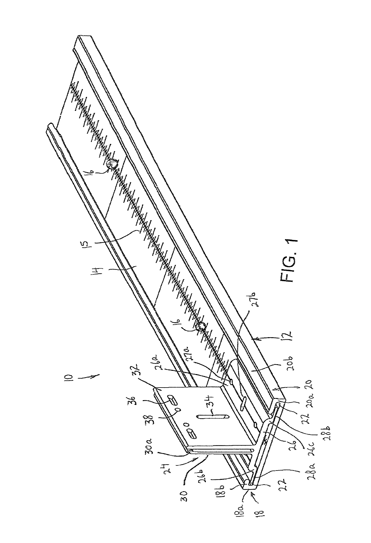
[0199]Referring to the drawings in detail, and initially to FIG. 1 thereof, there is shown a portion of a system 10 for easily mounting wall panels over an existing wall. System includes a base assembly including an elongated base support 12 that is adapted to be secured to an existing wall (not shown). Base support 12 includes an elongated base plate 14 having measuring gradations 15 along the upper surface thereof and openings 16 therealong through which screws (not shown) are adapted to extend to secure base plate 14 to the existing wall. L-shaped retaining walls 18 and 20 extend outwardly from opposite side edges of base plate 14. Specifically, each L-shaped retaining wall 18, 20 includes a first wall 18a, 20a that extends at a right angle from a side edge of base plate 14 and an inwardly extending second wall 18b, 20b that extends toward the opposite side edge of base plate 14 in parallel spaced apart relation to base plate 14 with a space 22 therebetween. Preferably, inwardly ...


PUM


Abstract

A system for mounting wall panels to an existing wall, includes adjustment support members secured to an existing wall and including a platform and a side wall extending from a side thereof and including elongated slots therein; connecting panels connecting together spaced apart adjustment support members, each connecting panel including a main panel and a side wall having a slot therein which opens at one edge of the side wall for receipt in an elongated slot; and a hook member including a securing section to which a wall panel is mounted, an L-shaped hook wall so as to receive a connecting panel in a space between the L-shaped hook wall and the securing section, and an adjustment arrangement for adjusting a position of the hook wall on the securing section so as to move the hook wall toward and away from the securing section.

Description

REFERENCE TO RELATED APPLICATION[0001]The present application is a Continuation-in-Part of U.S. patent application Ser. No. 15 / 655,278 filed Jul. 20, 2017 to the same inventor herein, and entitled SYSTEM FOR MOUNTING WALL PANELS TO A WALL, which in turn, is a Continuation-in-Part of U.S. patent application Ser. No. 15 / 488,897 filed Apr. 17, 2017 to the same inventor herein, and entitled SYSTEM FOR MOUNTING WALL PANELS TO A WALL, the entire disclosures of which are incorporated herein by reference.BACKGROUND OF THE INVENTION[0002]The present invention relates generally to a wall system, and more particularly, to a system for easily mounting wall panels over an existing wall.[0003]In order to enhance the look of a wall structure, it is known to secure wall panels to the wall structure. However, the securement of wall panels to the wall structure is generally a long and tedious job since it entails using fastening devices such as nails and / or screws to secure the walls panels directly ...

Claims


Application Information

Patent Timeline
Patent Type & Authority Patents(United States)
IPC IPC(8): E04F13/08E04F13/23E04B1/38
CPCE04F13/083E04F13/23E04F13/0801E04B2001/405E04F13/0817E04F13/0808E04F13/0825E04F13/0816E04B2001/389
Inventor BILGE, HENRY H.
Owner BILGE HENRY H
Why Eureka
Try Eureka