
Spinal Stabilization Systems and Methods

a technology of spinal stabilization and polyaxial fasteners, applied in the field of spinal stabilization systems, can solve the problems of destabilizing bone and affecting surrounding structures, pain and/or nerve damage, and altering the natural spacing between adjacent vertebra

Inactive Publication Date: 2008-11-20
ZIMMER SPINE INC
View PDF103 Cites 94 Cited by
  • Summary
  • Abstract
  • Description
  • Claims
  • Application Information

AI Technical Summary

Benefits of technology

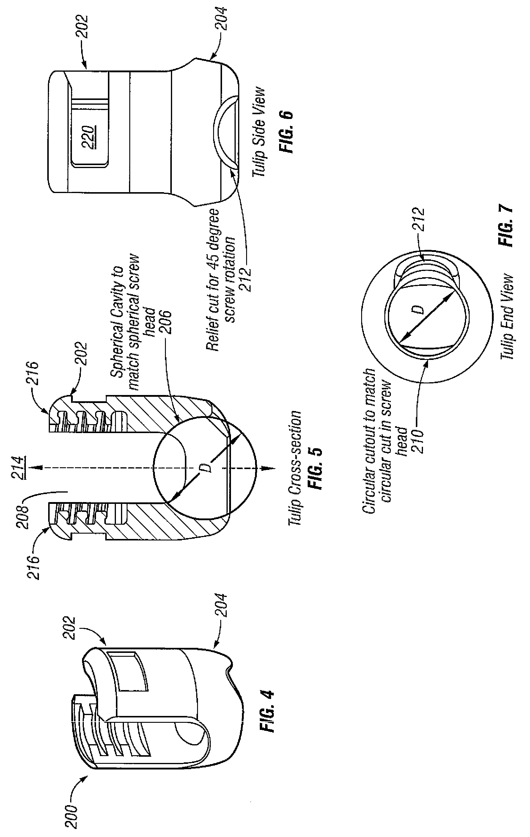
[0012]The invention also includes a spinal stabilization system that can be used to achieve rigid pedicle fixation while minimizing the amount of damage to surrounding tissue. In some embodiments, a spinal stabilization system can be used to provide stability to two or more vertebrae. A spinal stabilization system can include an elongated member, two or more bone fastener assemblies, and / or a closure member. The bone fastener assembly can include, but is not limited to, a bone fastener and a collar (or tulip). A first portion of the bone fastener can couple to a portion of the spine during use. A first portion of a collar (or tulip) includes a socket which can couple to a second portion of the bone fastener. A second portion of the collar can couple to an elongated member during use. In some embodiments, an orientation of the bone fastener can be independent of the orientation of the collar for a bone fastener assembly. After the bone fastener is placed in a vertebral body, the collar coupled to the bone fastener can be positioned so that the elongated member can be positioned in the collar and in at least one other collar that is coupled to another vertebral body by a bone fastener.
[0015]Further, once the fastener is received within the socket of the collar, separation of the fastener from the collar is inhibited by rotating the fastener to a different orientation with respect to the collar. Indeed, the fastener can be rotated substantially to any angle to reposition the first cross-sectional shape of the head portion out of alignment with the relief. The fastener therefore can be angulated, about a plurality of axes, within the collar (i.e., the bone fastener can move polyaxially relative to the collar within a defined range of motion) without risk of removal from the collar or the socket therein.
[0017]Inner surfaces of the arms of a bone fastener assembly collar can include a thread to engage a complementary thread of a closure member. A closure member secures the elongated member to the bone fastener assembly, and secures the position of the various components. In a preferred embodiment, a modified thread configuration is used.
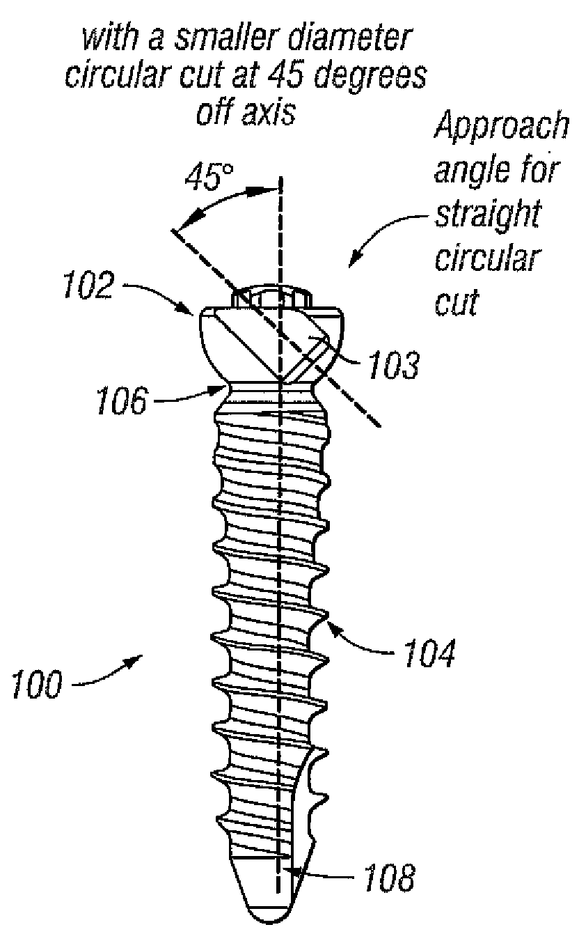
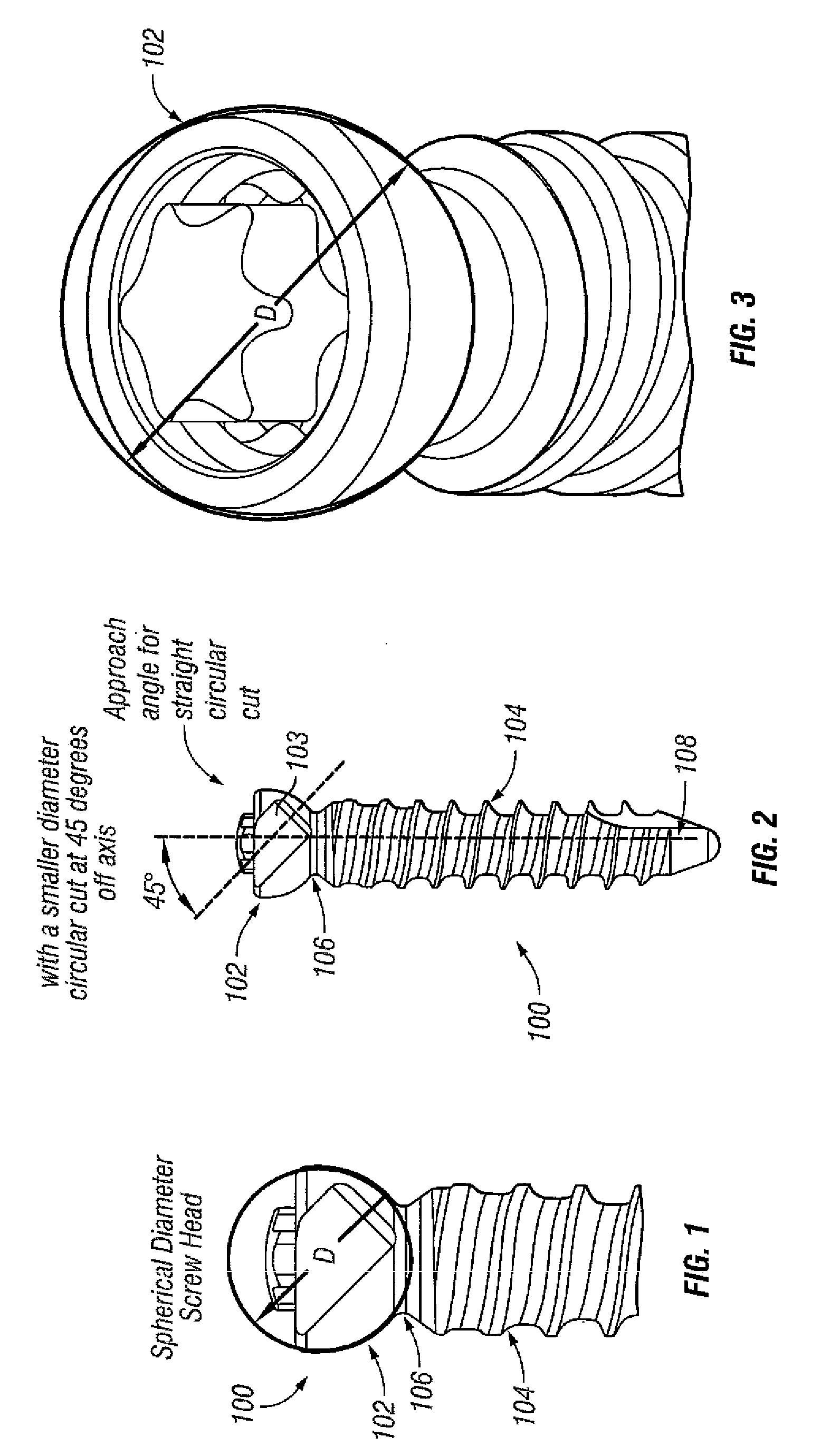
[0018]One embodiment provides a bone fastener including a collar, a fastener member, and a pin. The collar can have an upper portion with slot to receive an elongated member and a lower portion with a socket and an opening. The fastener member can have head and shank portions. The socket can receive the head portion and prevent movement of the head portion through the opening when the head portion is out of registration with the opening. The head portion and the socket can be configured to allow angulation of the fastener member within a defined range of motion within a selected plane. The head portion and the socket can define apertures which can be aligned with each other when the head portion is in the socket and which can receive the pin. One embodiment provides a generally spherical head portion with a flat.
[0021]The method can include creating an aperture in the body lower portion of the collar. An aperture can be created in an upper portion of the head portion of the fastener member in a location such that the aperture in the head portion of the fastener member aligns with the aperture in the lower portion of the collar when the head portion of the fastener member is in the socket. In some embodiments, movement of the head portion of the fastener member through the opening in the lower portion of the collar is prevented by inserting a pin coupled to the head portion of the fastener member through an aperture in the lower portion of the collar. Movement of the head portion of the fastener member through the opening in the lower portion of the collar by inserting a pin through apertures in the lower portion of the collar and the head portion of the fastener member.

Problems solved by technology

Degeneration can destabilize bone and affect surrounding structures.
For example, destabilization of a spine can result in alteration of a natural spacing between adjacent vertebrae.
Pressure applied to the nerves can cause pain and / or nerve damage.
Conventional procedures can result in trauma to the soft tissue, for example, due to muscle stripping.
Dissection and retraction of soft tissue can cause trauma to the soft tissue, and extend recovery time.

Method used


Image

  • Spinal Stabilization Systems and Methods
  • Spinal Stabilization Systems and Methods
  • Spinal Stabilization Systems and Methods

Examples


Embodiment Construction

[0056]Reference will now be made in detail to the present preferred embodiments of the invention, an example of which is illustrated in the accompanying drawings. The method and corresponding steps of the invention will be described in conjunction with the detailed description of the system.

[0057]A spinal stabilization system can be installed in a patient to stabilize a portion of a spine. Spinal stabilization can be used, but is not limited to use, in patients having degenerative disc disease, spinal stenosis, spondylolisthesis, pseudoarthrosis, and / or spinal deformities; in patients having fracture or other vertebral trauma; and in patients after tumor resection. A spinal stabilization system can be installed using a minimally invasive procedure. An instrumentation set can include instruments and spinal stabilization system components for forming a spinal stabilization system in a patient.

[0058]A minimally invasive procedure can be used to limit an amount of trauma to soft tissue ...


PUM


Abstract

One embodiment provides a bone fastener including a collar, a fastener member, and a pin. The collar can have an upper portion with slot to receive an elongated member and a lower portion with a socket and an opening. The fastener member can have head and shank portions. The socket can receive the head portion and prevent movement of the head portion through the opening when the head portion is out of registration with the opening. The head portion and the socket can be configured to allow angulation of the fastener member within a defined range of motion within a selected plane. The head portion and the socket can define apertures which can be aligned with each other when the head portion is in the socket and which can receive the pin. One embodiment provides a generally spherical head portion with a flat.

Description

CROSS-REFERENCE TO RELATED APPLICATIONS[0001]This application claims priority from U.S. patent application Ser. No. 11 / 959,063, filed Dec. 18, 2007, entitled “SPINAL STABILIZATION SYSTEMS AND METHODS,” which claims priority from provisional patent application No. 60 / 882,818, filed Dec. 29, 2006, entitled “SPINAL STABILIZATION SYSTEMS AND METHODS,” both of which are hereby fully incorporated herein for all purposes.BACKGROUND OF THE INVENTION[0002]1. Field of the Invention[0003]The present invention generally relates to a polyaxial fastener assembly, and spinal stabilization systems that include at least one polyaxial fastener. Embodiments of the invention relate to spinal stabilization systems that can be inserted into a patient preferrably using a minimally invasive surgical procedure. More particularly, embodiments disclosed herein relate to monoaxial fastener assembly created from a polyaxial fastener assembly. Embodiments of the invention relate to methods of assembling implant ...

Claims


Application Information

Patent Timeline
IPC IPC(8): A61B17/04
CPCA61B17/7032A61B17/7037A61B17/7038A61B17/8605
Inventor CRALL, ANGELAELY, KAMERON SCOTTRICEMAN, BRUCE A.
Owner ZIMMER SPINE INC
Learn More