Intervertebral implant with elastically deformable wedge

Inactive Publication Date: 2007-01-16
ZIMMER SPINE AUSTIN
View PDF18 Cites 517 Cited by
  • Summary
  • Abstract
  • Description
  • Claims
  • Application Information

AI Technical Summary

Benefits of technology

[0007]A problem which arises and which the present invention seeks to solve is thus how to make a spacer that serves not only to control progressive movement of vertebrae towards each ot

Problems solved by technology

Nevertheless, such a rigid spacer does not reproduce accurately the real physiological conditions under which relative movement between vertebrae is limited.
Nevertheless, the elastically deformable materials used that are suitable

Method used


Image

  • Intervertebral implant with elastically deformable wedge
  • Intervertebral implant with elastically deformable wedge
  • Intervertebral implant with elastically deformable wedge

Examples


Example

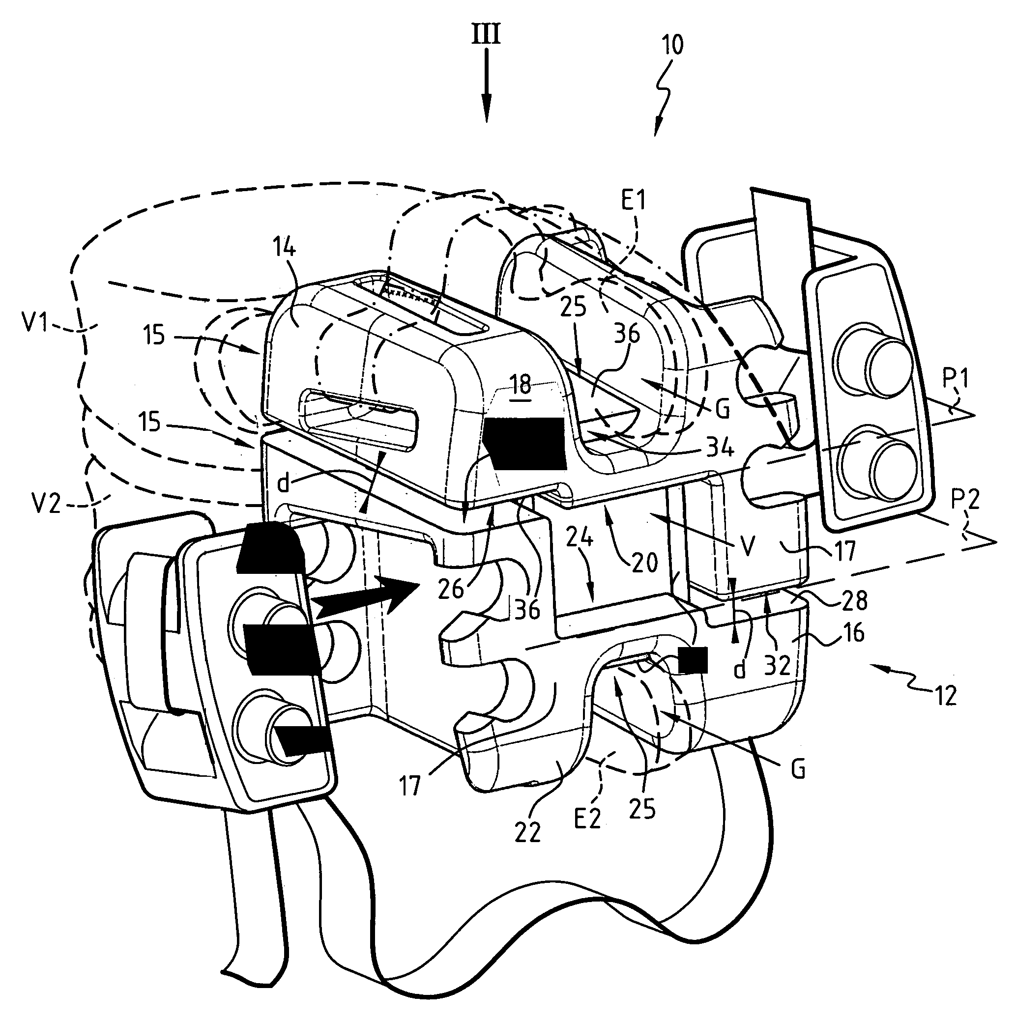
[0027]FIG. 1 shows an intervertebral implant 10 including a spacer 12 inserted between two spinous processes E1 and E2 of two respective vertebrae V1 and V2, drawn in fine dashed lines. The spacer 12 comprises two elements 14, 16 whose anterior walls 15 are disposed facing the vertebrae V1 and V2 of the spine, and whose posterior walls 17 face in the opposite direction. The first element 14 presents a first part 18 connected to the spinous process E1 and a second part 20 opposite the first part 18 serving for bearing purposes and defining a mean plane P1. The second element 16 likewise presents a first part 22 which is connected to the spinous process E2 and an opposite-second part 24 for bearing purposes defining a mean plane P2 and situated facing the bearing second part 20 of the first element 14. The first parts 18 and 22 of each element 14 and 16 are formed with a groove G with the spinous processes being engaged between the side walls thereof, which processes bear against the ...


PUM


Abstract

An intervertebral implant comprising a spacer for engaging between two spinous processes of two vertebrae of the spine. The spacer has two elements each presenting a first part suitable for being connected to a spinous process and bearing second parts opposite from the first part, the bearing second parts being situated facing each other. An elastically-compressible member is disposed between the bearing second parts. Links are provided which are distinct from the elastically-compressible member for linking together the two elements, the link member being suitable for blocking translation movement of the two elements relative to each other when the two elements are driven apart from each other.

Description

PRIORITY CLAIM[0001]This is a U.S. national stage of application No. PCT / FR02 / 04083, filed on 28 Nov. 2002. Priority is claimed on that application and on the following application: Country: France, Application No.: 01 15494, Filed: 30 Nov. 2001.BACKGROUND OF THE INVENTION[0002]1. Field of the Invention[0003]The present invention relates to an intervertebral implant including a spacer for being applied between two spinous processes of two vertebrae of the spine.[0004]2. Discussion of Related Art[0005]Well-known intervertebral implants comprise a spacer for inserting between the spinous processes which extend the posterior portions of vertebrae in order to limit and control relative displacement of the vertebrae relative to one another. Such implants are generally installed on the spine of a patient suffering from a degenerative pathology of the spine in which the vertebrae run the risk of approaching one another and, for example, of compressing the roots of nerves. A first category ...

Claims


Application Information

Patent Timeline
IPC IPC(8): A61F2/44A61B17/58A61B17/70
CPCA61B17/7062A61F2/44
Inventor SENEGAS, JACQUESLE COUEDIC, REGIS
Owner ZIMMER SPINE AUSTIN
Why Eureka
Try Eureka