Portable chamfering machine

A chamfering machine, portable technology, applied in the directions of portable mobile devices, milling machine equipment details, metal processing equipment, etc., can solve problems such as consideration and increase the burden of operators

Inactive Publication Date: 2009-09-16
NITTO KOHKI CO LTD
View PDF1 Cites 5 Cited by
  • Summary
  • Abstract
  • Description
  • Claims
  • Application Information

AI Technical Summary

Problems solved by technology

Especially when machining the inner peripheral part of the hole, since it is impossible to visually see when the cutting insert touches the chamfering part, it is necessary to prevent the impact caused by inadvertent contact, and at the same time, it is necessary to slowly move the chamfering machine while using a strong grip. The surface of the workpiece is advanced so that chipping due to impact does not occur, which is the main cause of increasing the burden on the operator
In the invention described in Patent Document 1, such problems are not considered

Method used


Image

  • Portable chamfering machine
  • Portable chamfering machine
  • Portable chamfering machine

Examples


Embodiment Construction

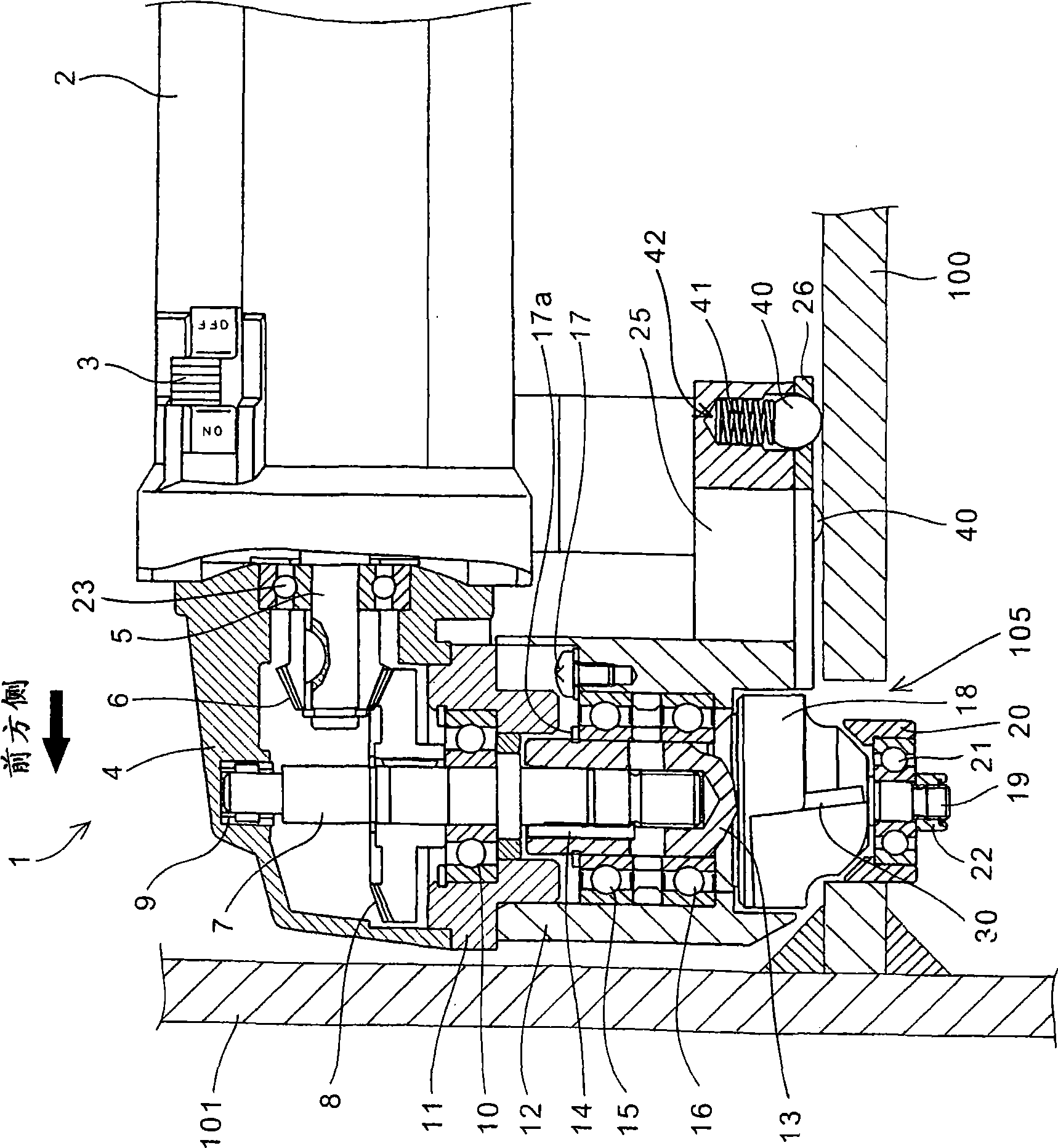
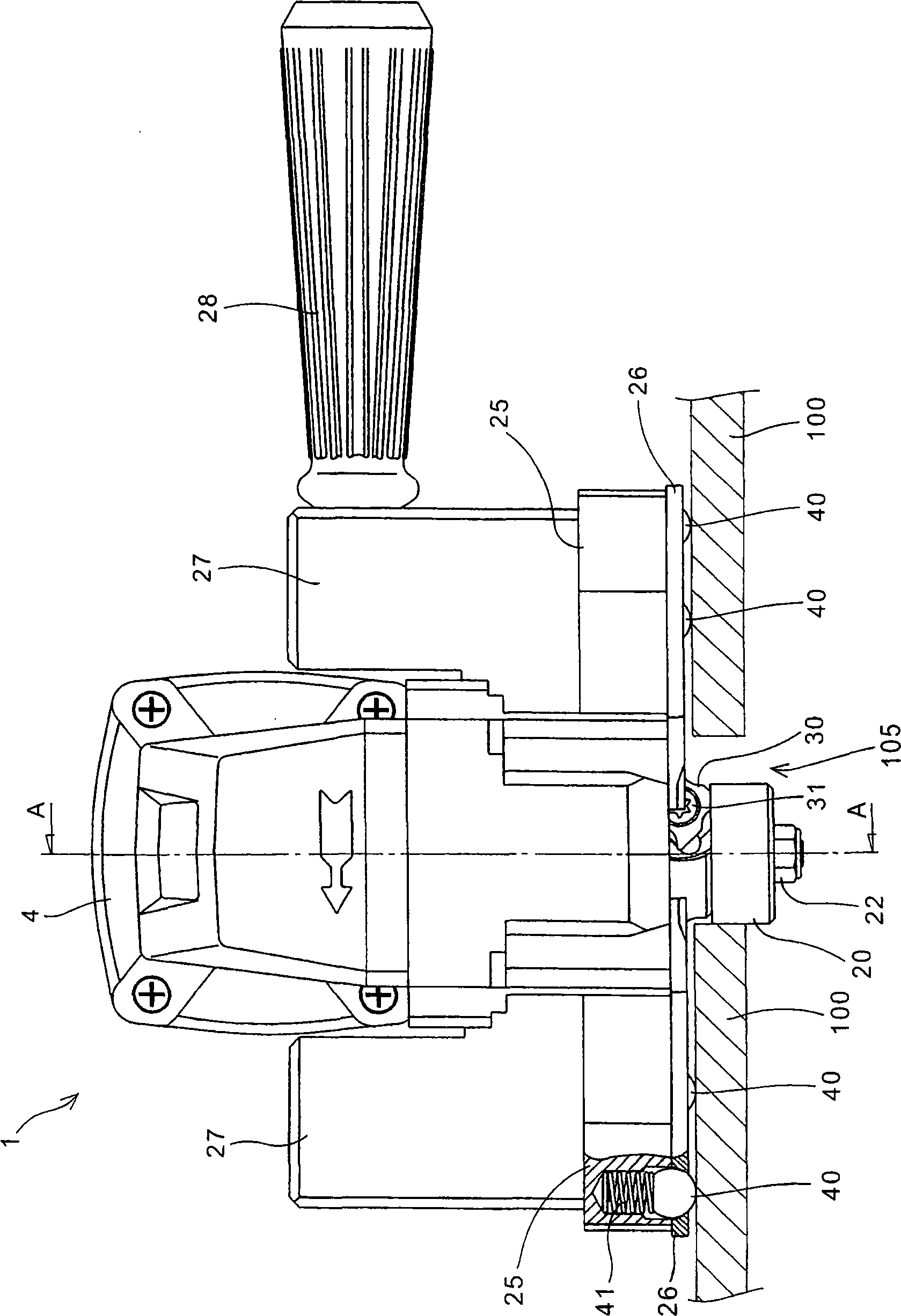
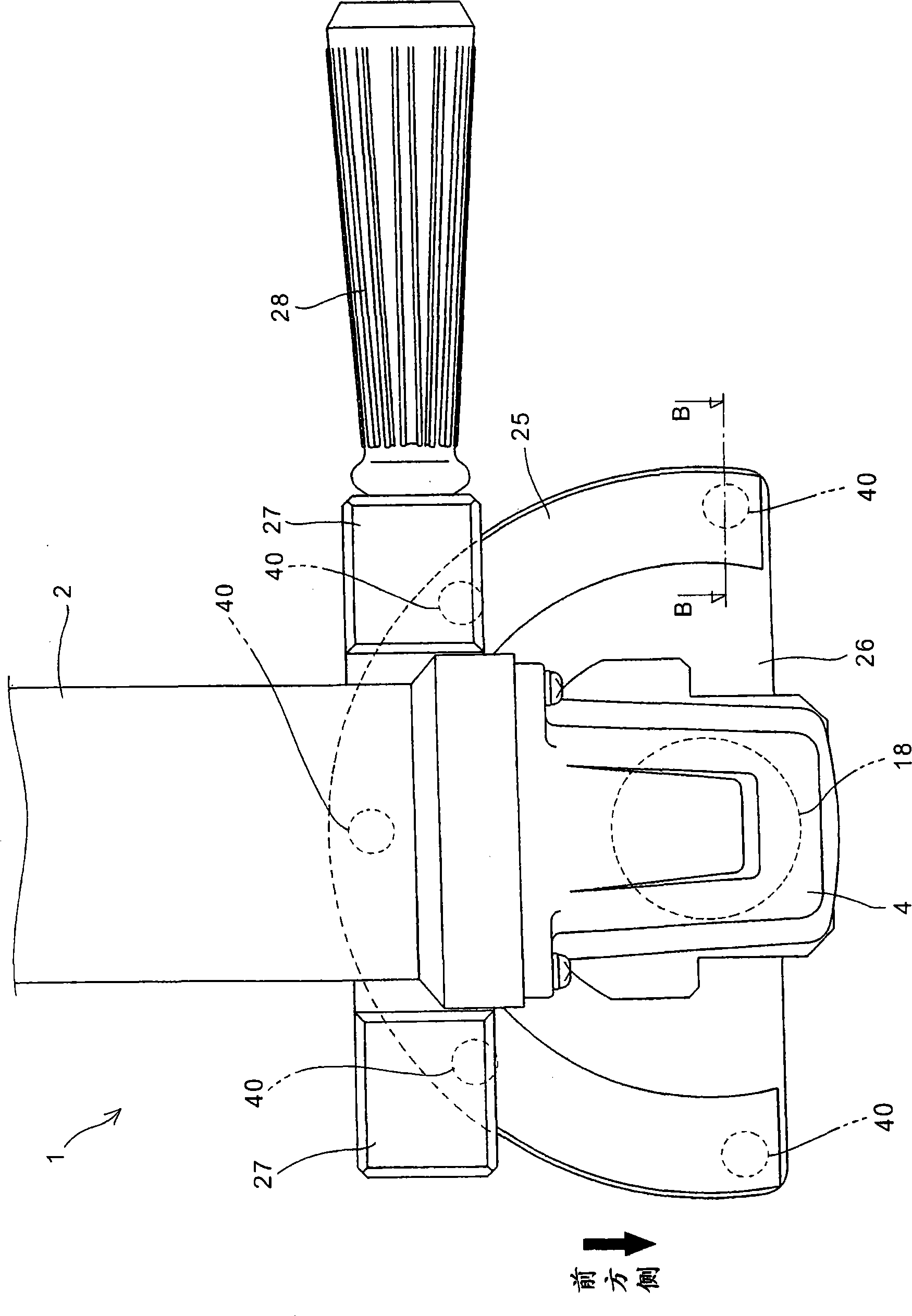
[0035] Hereinafter, preferred embodiments of the present invention will be described in detail with reference to the drawings. figure 1 It is a partially cutaway side view of a portable chamfering machine 1 according to an embodiment of the present invention. figure 2 It is a front view of the portable chamfering machine 1. in addition, image 3 and Figure 4 It is a plan view and a bottom view of the portable chamfering machine 1. in addition, figure 1 The section section contains figure 2 A-A line section section.

[0036] The portable chamfering machine 1 is an electric tool capable of chamfering the outer peripheral end of a workpiece and the inner peripheral part such as a hole or a groove by using a cutting blade 30 mounted on a rotating shaft 7 protruding from the lower side of a housing 4. Corner processing. In this embodiment, a state in which the inner peripheral portion of the hole 105 provided in the plate-like workpiece 100 is chamfered is shown. In addi...


PUM


Abstract

A portable chamfering machine which can perform chamfering at a desired set amount with good productivity while preventing a cutting tip from being chipped without increasing burden on a worker. The portable chamfering machine (1) has a cutting tip (30) fixed to a rotating shaft (7) projecting from a casing (4). The portable chamfering machine comprises a guide plate (26) secured to the casing (4) toward the direction perpendicular to the rotating shaft (7) and coming into contact with the upper surface (100a) of a member (100) to be processed; a guide roller (20) supported at the end of the rotating shaft (7) and coming into contact with the side surface (105a) of a hole (105); and a steel ball (40) projected from the guide plate (26) by the urging force of a spring (41) to form a predetermined clearance between the upper surface (100a) and the guide plate (26). When the clearance is formed, the member can be processed with a chamfering amount smaller than a desired set amount, and the member can be processed with a desired set amount by pressing the portable chamfering machine (1) against the urging force and bringing the guide plate (26) into contact with the upper surface (100a).

Description

technical field [0001] The present invention relates to a portable chamfering machine, and more particularly to a portable chamfering machine capable of preventing chipping of cutting inserts and performing chamfering at a desired set amount with high productivity without increasing the burden on the operator. Background technique [0002] Conventionally, there is known a portable chamfering machine capable of chamfering the outer peripheral end portion of a workpiece and the inner peripheral portion of a hole or groove with a cutting insert attached to a rotating shaft protruding from a housing. [0003] In Patent Document 1, a portable chamfering machine is disclosed, which has a guide plate fixed on the casing and a guide roller freely rotatably installed at the end of the rotating shaft, by stacking By placing the guide plate under the guide roller and moving it while pushing the outer peripheral portion of the guide roller toward the end surface (side surface) of the wo...

Claims


Application Information

Patent Timeline
Patent Type & Authority Applications(China)
IPC IPC(8): B23C3/12B25F5/02
CPCB23C3/126
Inventor 村上庆一白井敦齐藤升
Owner NITTO KOHKI CO LTD
Why Eureka
Try Eureka