To water treatment systems

a technology of flow control and water treatment system, which is applied in water/sludge/sewage treatment, water treatment parameter control, mixer, etc., can solve the problems of toxic effects on plants or animals, under-dosing may not achieve what the additive is used, and potentially serious consequences

Inactive Publication Date: 2011-09-08
PETA ENTERPRISES
View PDF4 Cites 6 Cited by
  • Summary
  • Abstract
  • Description
  • Claims
  • Application Information

AI Technical Summary

Benefits of technology

[0086]The potentially realisable advantage of such movement is that a permitted degree of movement can help bubbles and foreign particles to negotiate through the baffle arrangement and exit through the outlet. This movement may be induced by localised pressure build up or flow reduction due to an obstructing particle, by the normal flow of fluid, and / or physical movement transmitted from the environment that the fluid flow control assembly is in. This movement therefore helps the fluid flow control assembly to become self cleaning for most minor obstructions, though ideally a separate filter is used to remove large particles.
[0087]Ideally the movement of moveable baffle elements is restrained or restricted. The internal chamber itself may be sufficient to contain the baffle elements. Features on the internal wall of the internal chamber may help individually or collectively locate baffle elements. In a preferred embodiment a restraining element, comprising a wire, links the baffle elements. This string of baffle elements may move freely within the internal chamber, though again movement may be limited by the size and dimensions of the internal chamber. Such a wire or restraining element may be flexible, and may be elastic in nature to bias the baffle elements towards each other. Other arrangements (e.g. compressible elastic members between each end of the baffle arrangement and end walls of the internal chamber) may also be used to bias the baffle elements towards each other.

Problems solved by technology

In each case, overdosing can have toxic effects on the plant or animal, while under-dosing may not achieve what the additive is used for.
Hence there is an optimum window in many cases, with potentially serious consequences if one doses outside of that window.
While the previous invention was successful in the field for its intended application (animal water troughs), one limitation was that it tended to hold and dispense only one to two day's dosage.
Scaling up the size of the reservoir was not always practical as this could also affect diffusion rates and hence additive dosing rates.
Unfortunately there are some practical issues associated with very small control jet apertures.
One practical issue that sometimes occurred was the occasional presence of air bubbles in the system blocking the jets with an airlock.
As the system relied on the pressure from the convection of different density layers of fluid (rather than water inlet pressure from a pipe), the system could not always self clear these bubbles.
Reducing the size of jet apertures further, to extend the time between refilling the additive reservoir, only increased the problem of air bubble airlocks.
As these devices were used in the field under sometimes difficult conditions, the vibrations (of filling, or lifting the device from a trough) were as likely to introduce air bubbles and to dislodge them.

Method used


Image

  • To water treatment systems
  • To water treatment systems
  • To water treatment systems

Examples


Embodiment Construction

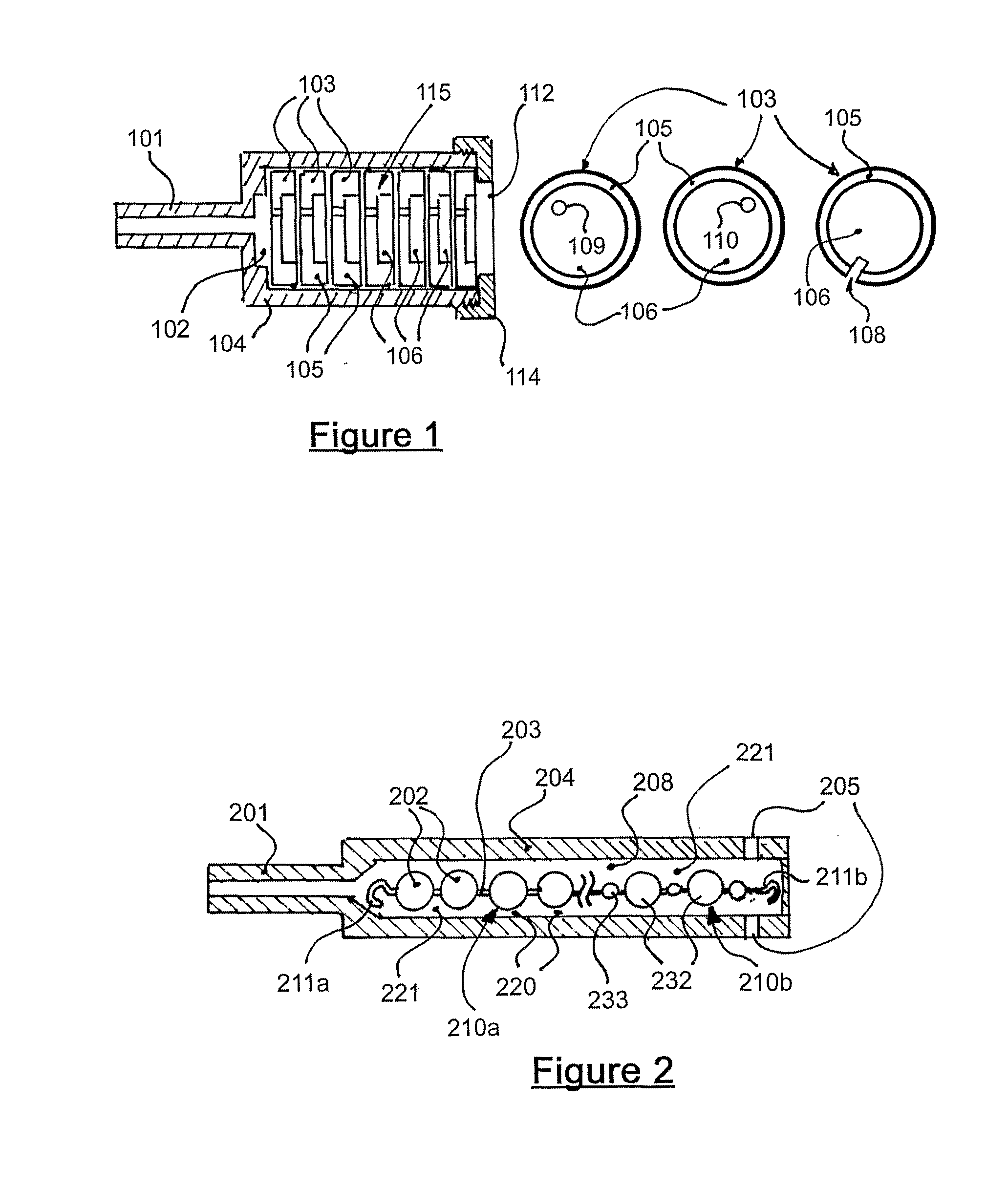
[0107]FIG. 1 illustrates one embodiment of a fluid flow control assembly according to the present invention. The fluid flow control assembly comprises a body of two pieces (104, 114) which may be of plastic or metal. The body (104, 114) defines an internal chamber (102). At one end is an inlet aperture (112) and at the distal end an outlet (101) through the device is non-directional and may be used either way around (e.g. aperture (101) may be the inlet)).

[0108]Within the internal chamber (102) is a baffle arrangement (generally indicated by arrow 115) comprising a plurality of baffle elements (103). Each baffle element (103) comprises a plate-like element having a raised annular ridge (105) defining a recessed central cavity region (106). Apertures (109) and (110) are placed in alternate positions to make the flow of fluid through the baffle elements (103) more tortuous. Additionally or instead of apertures (109, 110), channels (108) in the outer edge of each element may be provide...


PUM

PropertyMeasurementUnit
areaaaaaaaaaaa
areaaaaaaaaaaa
areaaaaaaaaaaa

Abstract

The present invention is directed to a fluid flow control assembly for regulating fluid flow, and may find particular application in additive dispenser systems. Typically a baffle arrangement (210) comprises a plurality of baffle elements (202) within a chamber (208). The arrangement forms an alternating sequence of restrictions and cavities for fluid flowing from an inlet (205) to an outlet (201) and tends to restrict fluid flow in an alternative manner to merely providing a fine diameter aperture. The fluid flow control assembly was developed for applications where foreign particles or air bubbles may block fine diameter apertures, such as low pressure additive dispenser systems where low relatively stable flow rates are important to their operation.

Description

FIELD OF INVENTION[0001]The present invention is generally directed to fluid flow control assemblies for low fluid flows, and their use in dispenser arrangements for the incorporation of additives to a fluid supply.BACKGROUND DESCRIPTION[0002]The applicant has previously invented an additive for dispensing solid additives to animal troughs and water supplies. This is the subject of NZ Patent 202233. This dispensing system comprised an additive reservoir and a dosing chamber separated by a plurality of apertures. Water from the dosing chamber would slowly diffuse into the additive reservoir to mix with solid additive therein. A solution of additive would generally diffuse back into the dosing chamber. An inlet and outlet were provided in the dosing chamber to allow water (from a supply) to enter the dosing chamber, and to exit into a trough or water supply. The rate by which additive was introduced to the trough or supply was proportional largely on the rate of diffusion of solution ...

Claims


Application Information

Patent Timeline
Patent Type & Authority Applications(United States)
IPC IPC(8): C02F1/50
CPCA01K7/02C02F2209/40B01F1/0038B01F5/0498B01F5/0604B01F5/061B01F2005/0631B01F2005/0637C02F1/50C02F1/68C02F1/685C02F1/686C02F1/687C02F1/688C02F2209/001B01F1/0033B01F21/30B01F21/221B01F25/32B01F25/422B01F25/431B01F25/4319B01F25/431972
Inventor PHILLIPS, DOUGLAS STEWARD MORELANDPHILLIPS, PETER ALFRED JOHN
Owner PETA ENTERPRISES
Why Eureka
Try Eureka