Tubular door lock having selective actuators

Inactive Publication Date: 2005-03-31
LIANG ALAN +2
View PDF13 Cites 6 Cited by
  • Summary
  • Abstract
  • Description
  • Claims
  • Application Information

AI Technical Summary

Benefits of technology

[0014] The housing includes a stud extended therein and engaged into the groove of the follower, to guide the follower to move relative to the housing

Problems solved by technology

However, the spring members may not solidly retain the actuator wheel to the plat

Method used


Image

  • Tubular door lock having selective actuators
  • Tubular door lock having selective actuators
  • Tubular door lock having selective actuators

Examples


Example

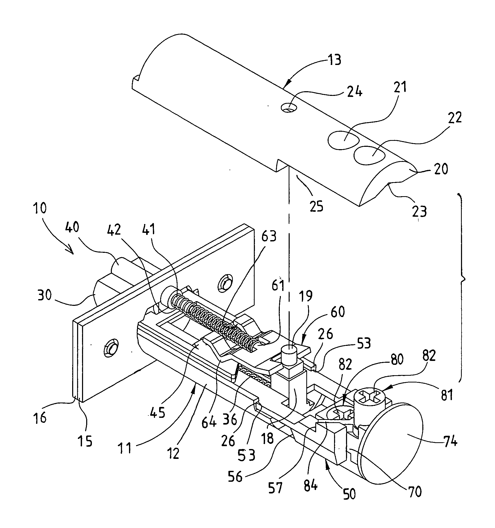
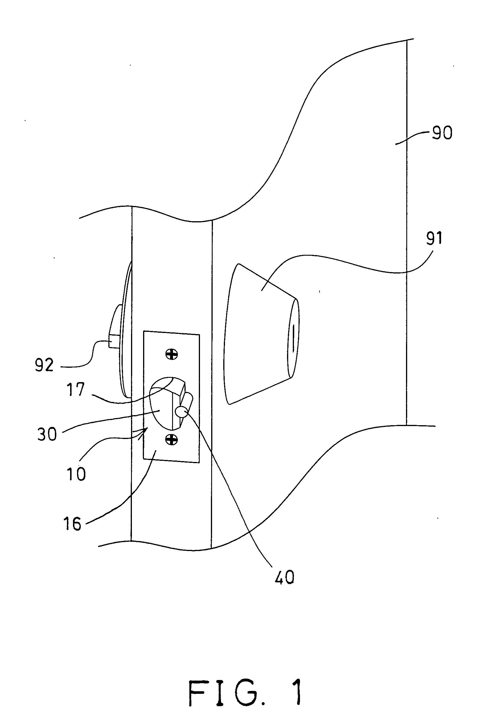
[0022] Referring to the drawings, and initially to FIG. 1, a tubular door lock 10 in accordance with the present invention is provided for attaching into a door panel 90, and comprises a dead bolt 30 and a latch 40 to be actuated or operated with a lock device 91 and a knob 92. The dead bolt 30 includes a slot 31 formed therein (FIG. 4) to slidably receive the latch 40 therein.

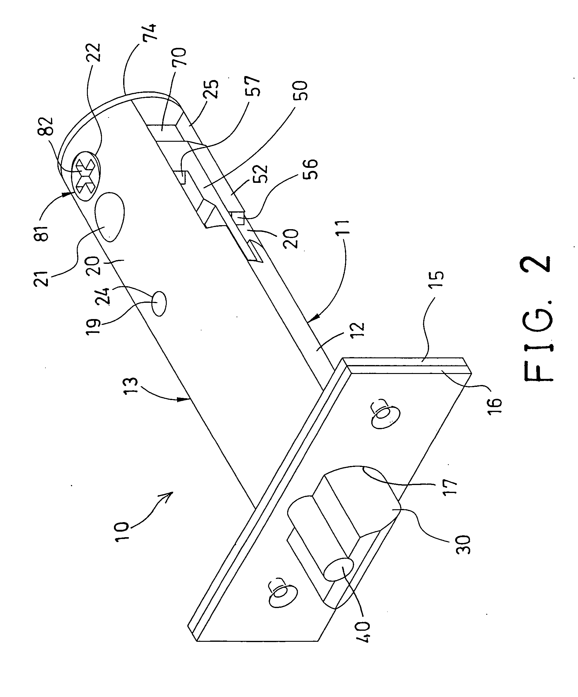
[0023] As shown in FIGS. 2-5, the tubular door lock 10 includes a cylindrical housing 11 formed by such as two housing members 12, 13 that may be secured together with fasteners, latches (not shown), adhesive materials, or by welding processes, or the like, and one or more plates 15, 16 secured to the front portion of the housing 11 for attaching or securing to the door panel 90.

[0024] The above-described structure of the cylindrical housing 11 and the dead bolt 30 and the latch 40 and the lock device 91 and the knob 92 is typical and will not be described in further details. The tubular door lock 10 is prov...


PUM


Abstract

A tubular door lock includes a dead bolt and a follower slidably received in a housing and coupled together. The follower included a groove formed between two levers, two actuators are rotatably received in the housing and each includes one or more actuating fingers engageable with the levers of the follower, for selectively actuating the levers of the follower to move the dead bolt relative to the housing, when the actuators are rotated relative to the housing. The provision of the actuators in different positions relative to the housing allows the lock device or the knob to engage with either of actuators, for allowing the lock device and the knob to be secured into the door panel at different positions.

Description

BACKGROUND OF THE INVENTION [0001] 1. Field of the Invention [0002] The present invention relates to a tubular door lock, and more particularly to a tubular door lock having selective actuators for fitting to different door panels. [0003] 2. Description of the Prior Art [0004] Typical tubular door locks comprise a pair of extensions extended from a cylindrical housing and coupled to dead bolts, and an actuator wheel rotatably attached to the cylindrical housing and having one or more actuator teeth for engaging with the extensions of the cylindrical housing, and actuating or moving the dead bolts into the cylindrical housing. [0005] For example, U.S. Pat. No. Re. 34,240 to Lin, U.S. Pat. No. 5,257,838 to Lin, and U.S. Pat. No. 5,354,109 to Lin disclose three of the typical tubular door locks comprise an actuator wheel rotatably attached to a pair of plates of the cylindrical housing, and slidable or adjustable relative to the plates of the cylindrical housing, for allowing the typic...

Claims


Application Information

Patent Timeline
IPC IPC(8): E05B9/00E05B55/00E05B63/06E05B63/20E05C1/12
CPCE05B55/005Y10S292/60E05B63/06Y10T292/06Y10T292/62Y10T292/564
Inventor PENG, FU CHANGLIANG, ALANHSIAO, CHIH HUNG
Owner LIANG ALAN
Why Eureka
Try Eureka