Antenna device

Inactive Publication Date: 2017-03-02
MITSUMI ELECTRIC CO LTD
View PDF4 Cites 16 Cited by
  • Summary
  • Abstract
  • Description
  • Claims
  • Application Information

AI Technical Summary

Benefits of technology

[0009]It is, therefore, a main object of the present invention is to improve the strength of an antenna device,

Problems solved by technology

However, if the entire base is formed by die casting, the antenna device becomes heavy and the cost will also be expensive.
However, since sheet metal components have low rigidity and there are great number of sheet metal components, it is difficult to form a complicate shape.
However, since the conductive base is embedded in the insulated base in the antenna device of JP 5654917, strength of the connection between the insulated base and the conductive base is weak and there is a possibil

Method used


Image

  • Antenna device
  • Antenna device
  • Antenna device

Examples


Embodiment Construction

[0033]Hereinafter, an embodiment of the present invention will be described with reference to the drawings. However, the present invention is not limited to the examples shown in the drawings.

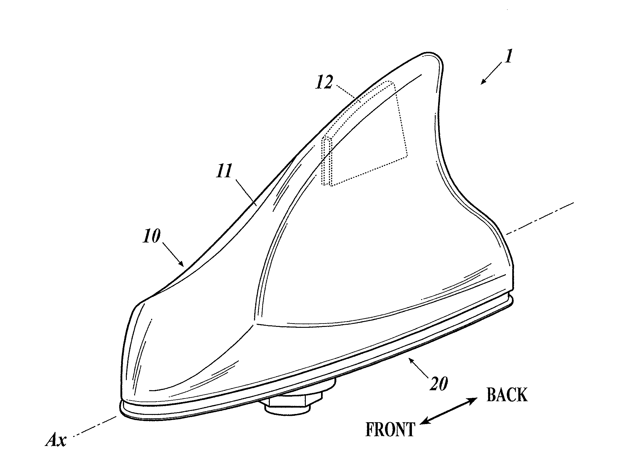
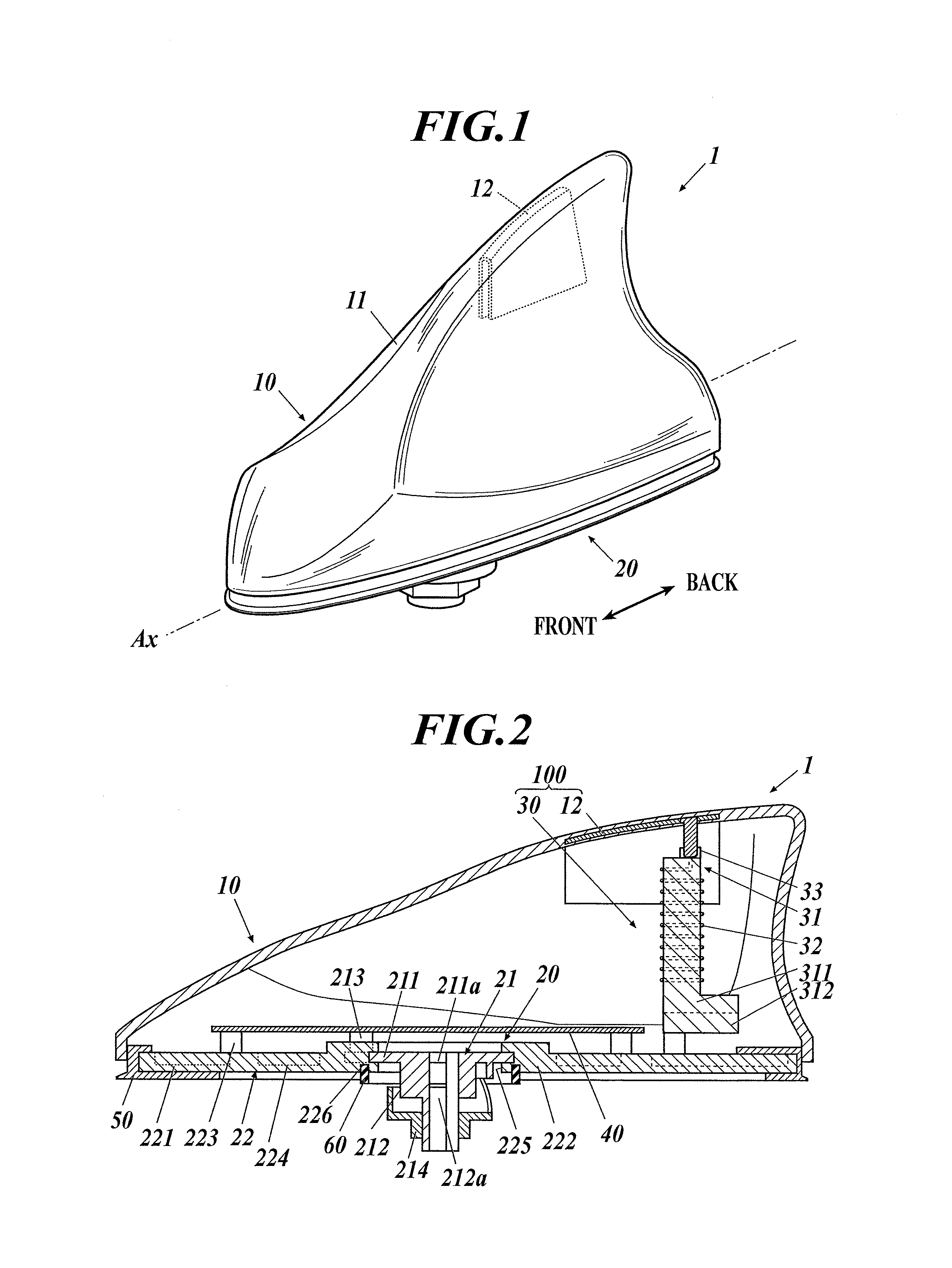
[0034]FIG. 1 is an external view of an antenna device 1 according to the embodiment. FIG. 2 is a cross-sectional view of the internal structure of the antenna device. The antenna device 1 of the embodiment is an antenna device which can receive radio waves of a frequency band for AM / FM broadcasting. For example, the antenna 1 is an on-vehicle antenna device which is mounted and fixed to the mounting surface on the roof of a vehicle.

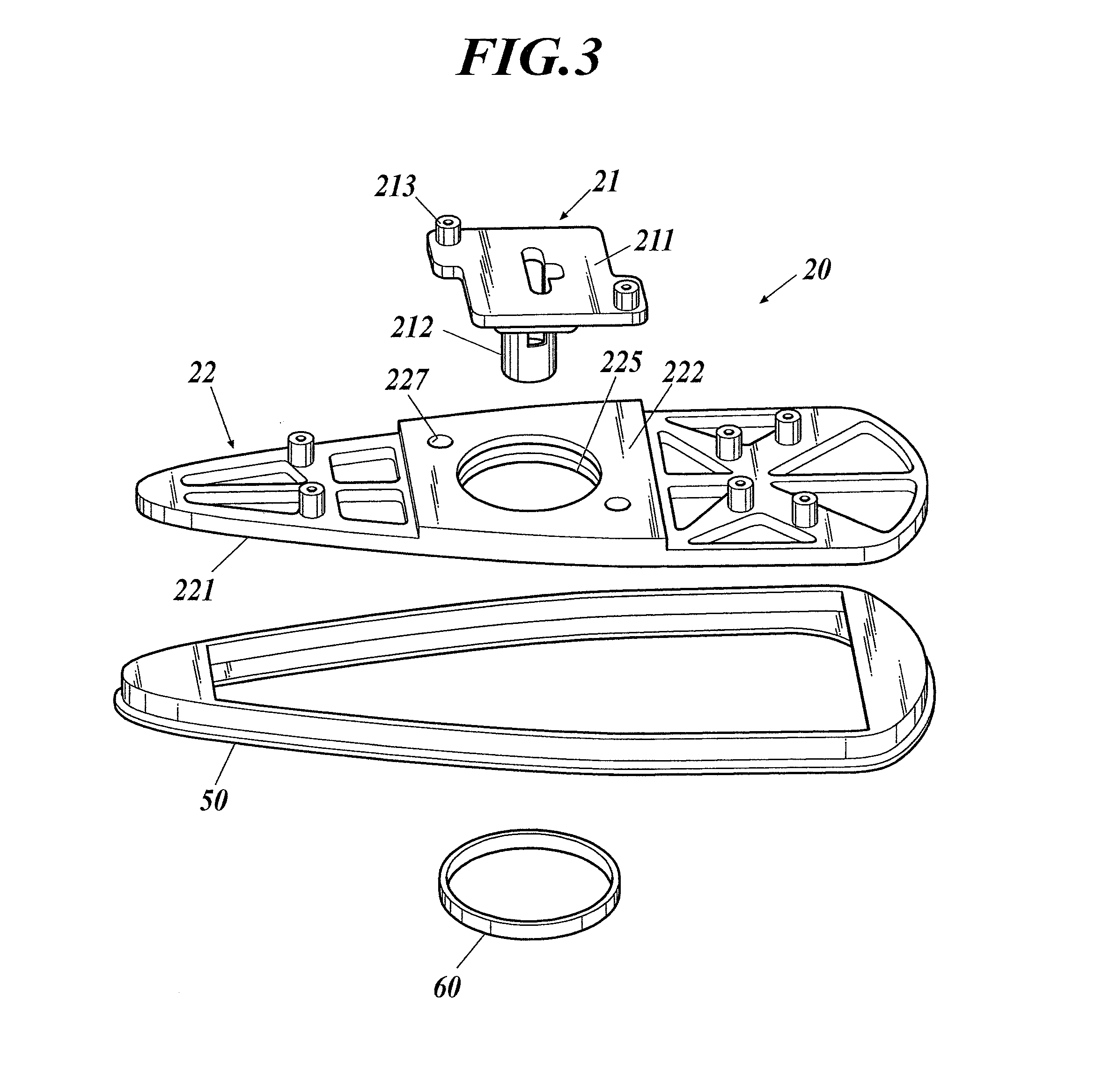
[0035]As shown in FIGS. 1 and 2, the antenna device 1 includes an antenna cover 10, an antenna base 20, an antenna unit 30, an antenna board 40, a gasket 50 and a packing 60. The antenna unit 30 is part of an antenna to receive radio waves from AM / FM broadcast stations.

[0036]As shown in FIG. 1, the antenna cover 10 includes a cover body 11 and a capacitive element 12...


PUM


Abstract

An antenna device includes an antenna base, an antenna cover attached to the antenna base and an antenna unit. The antenna base includes a metallic die-cast base and a resin base. The die-cast base includes a protrusion which is to be inserted in a fixing opening formed in a vehicle and attached to the vehicle, and the die-cast base and the resin base are molded integrally.

Description

BACKGROUND OF THE INVENTION[0001]1. Field of the Invention[0002]The present invention relates to an antenna device.[0003]2. Description of the Related Art[0004]Conventionally, there has been known an on-vehicle antenna device (shark fin antenna) which is called the shark fin shaped antenna due to its external appearance having a shape like a shark's fin (see Japanese Unexamined Patent Application Publication (Translation of PCT Application) No. 2009-514253). With respect to such antenna device, an antenna such as a GPS (Global Positioning System) is disposed on a base and a housing cover having a shark fin shape is attached to the base so as to include the antenna inside thereof.[0005]As a shark fin antenna, there is also known an antenna device having a single die-cast base which is formed by metal die casting. However, if the entire base is formed by die casting, the antenna device becomes heavy and the cost will also be expensive.[0006]In view of the above, as a shark fin antenna...

Claims


Application Information

Patent Timeline
IPC IPC(8): H01Q1/32H01Q1/36H01Q1/48
CPCH01Q1/3275H01Q1/362H01Q1/48H01Q1/12H01Q1/22H01Q1/36H01Q1/42H01Q1/1214H01Q1/32H01Q1/405
Inventor MASAKA, YOSHINORINORO, JUNICHI
Owner MITSUMI ELECTRIC CO LTD
Why Eureka
Try Eureka