This helps you quickly interpret patents by identifying the three key elements:
Problems solved by technology
Method used
Benefits of technology
Benefits of technology
The patent text describes a controller that can control multiple lighting devices using a single sensor to maintain constant brightness in a room. The controller takes into account the environment where the lighting devices are installed to ensure appropriate control. The lighting system includes the lighting devices and the controller. The technical effect is to provide an efficient and effective way to control multiple lighting devices using a single sensor.
Problems solved by technology
Accordingly, the illumined space formed by light from the lighting devices may be maintained in an unnatural state for a long time.
Method used
Image
Click on the blue label to locate the original text in one second.
Reading with bidirectional positioning of images and text.
Examples
embodiment 1
[0032]The following describes a lighting system according to Embodiment 1.
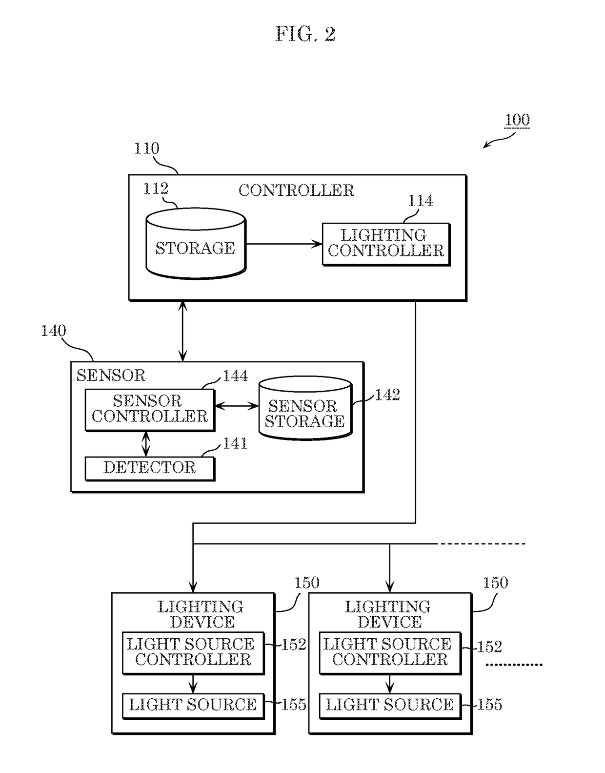
[0033]First, a description of a configuration of a lighting system according to Embodiment 1 is given with reference to FIGS. 1A, 1B, 2, and 3.
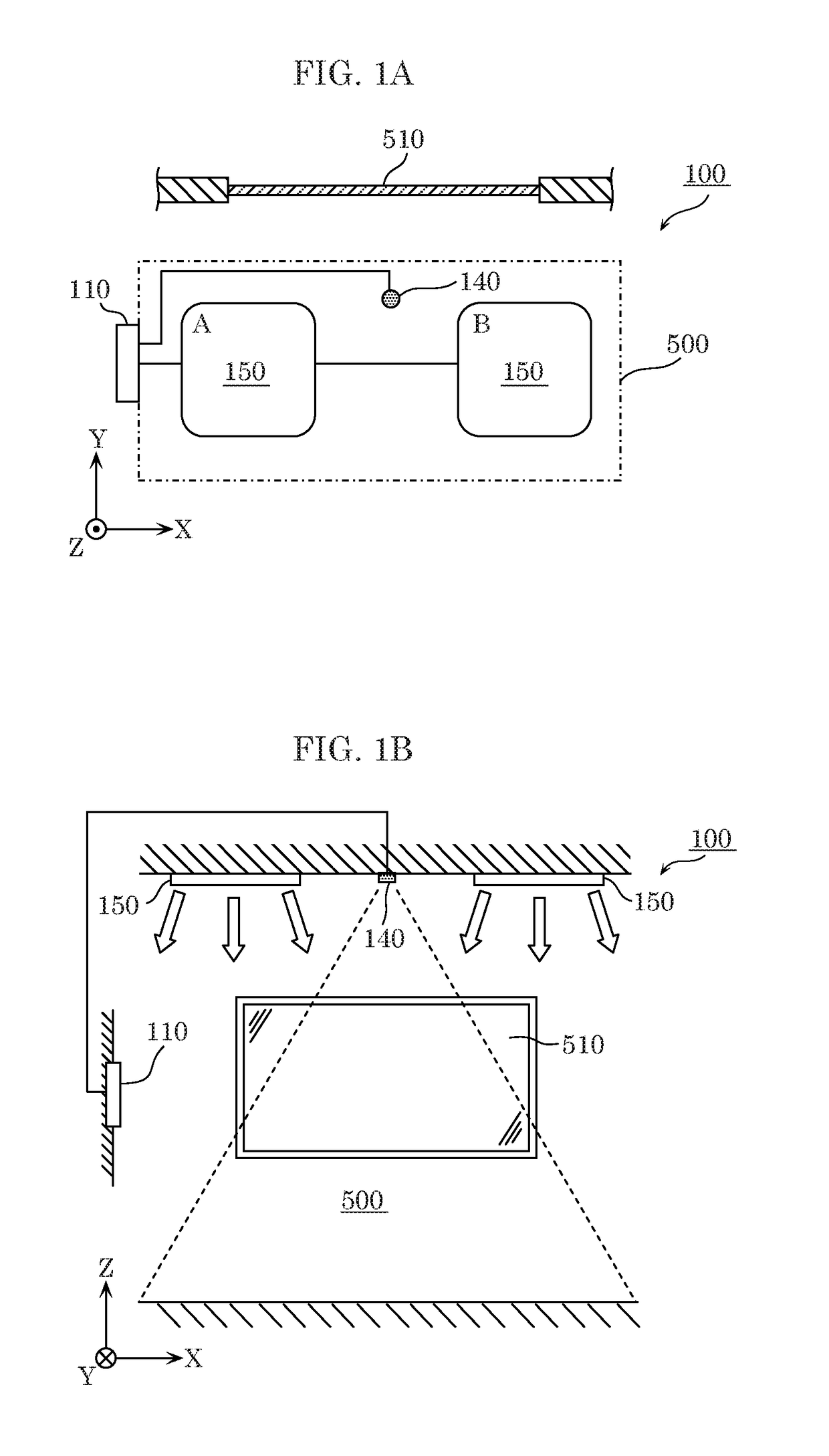
[0034]FIG. 1A is a first diagram illustrating a schematic configuration of lighting system 100 according to Embodiment 1, and FIG. 1B is a second diagram illustrating a schematic configuration of lighting system 100 according to Embodiment 1.
[0035]Specifically, FIG. 1A is a top view illustrating an example of the layout of elements of lighting system 100, and FIG. 1B is a side view corresponding to FIG. 1A. Note that depictions of the lines that connect controller 110 and lighting devices 150 are omitted from FIG. 1B. While lighting system 100 is installed in a space (room) which needs lighting such as, for example, a room in an office building or a house, depictions of objects which may be present in the space, such as fixtures and per...
embodiment 2
[0089]The following describes a lighting system according to Embodiment 2, focusing on a difference from Embodiment 1 above.
[0090]FIG. 5A is a first diagram illustrating a schematic configuration of lighting system 100a according to Embodiment 2, and FIG. 5B is a second diagram illustrating a schematic configuration of lighting system 100a according to Embodiment 2.
[0091]Specifically, FIG. 5A is a top view illustrating an example of the layout of elements of lighting system 100a, and FIG. 5B is a side view corresponding to a portion of FIG. 5A.
[0092]FIG. 6 is a block diagram illustrating a functional configuration of lighting system 100a according to Embodiment 2. FIG. 7 illustrates an example of a data configuration of first grouping information 270 stored in storage 112 according to Embodiment 2.
[0093]As illustrated in the drawings, lighting system 100a according to Embodiment 2 includes a plurality of lighting devices 150, controller 110a, and se...
PUM
Abstract
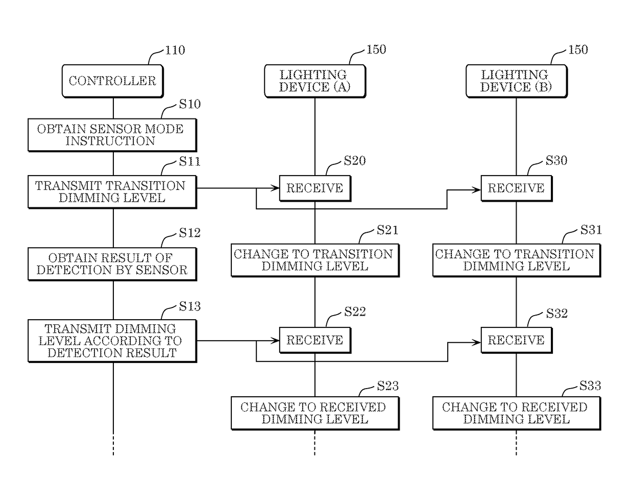
A lighting system includes: a plurality of lighting devices; a controller; and a sensor which detects brightness of a region illuminated by at least two lighting devices among the plurality of lighting devices, wherein the controller includes a lighting controller operable in a plurality of operation modes, the plurality of operation modes include a sensor mode, and when the lighting controller obtains an instruction to operate in the sensor mode, the lighting controller performs (a) transition control for controlling the at least two lighting devices, by transmitting a transition instruction, to cause the at least two lighting devices to provide illumination at a predetermined dimming level, without using a result of detection by the sensor, and (b) dimming control for controlling the at least two lighting devices to cause the brightness indicated by the result of detection by the sensor to approach the target value, after transmitting the transition instruction.
Description
CROSS REFERENCE TO RELATED APPLICATION[0001]This application claims the benefit of priority of Japanese Patent Application Number 2016-002998 filed on Jan. 8, 2016, the entire content of which is hereby incorporated by reference.BACKGROUND[0002]1. Technical Field[0003]The present disclosure relates to a controller which controls a plurality of lighting devices, and a lighting system which includes the plurality of lighting devices and the controller.[0004]2. Description of the Related Art[0005]Conventionally, a lighting control device has been known which controls a dimming level of a lighting device such as an LED light on the ceiling.[0006]For example, according to a lighting control device disclosed in Japanese Unexamined Patent Application Publication No. 2015-079695, an illuminance sensor detects the illuminance of a first region close to an open portion of a room. According to the detection result, the lighting control device further changes the dimming level of a lighting dev...
Claims
Application Information
Patent Timeline
Application Date:The date an application was filed.
Publication Date:The date a patent or application was officially published.
First Publication Date:The earliest publication date of a patent with the same application number.
Issue Date:Publication date of the patent grant document.
PCT Entry Date:The Entry date of PCT National Phase.
Estimated Expiry Date:The statutory expiry date of a patent right according to the Patent Law, and it is the longest term of protection that the patent right can achieve without the termination of the patent right due to other reasons(Term extension factor has been taken into account ).
Invalid Date:Actual expiry date is based on effective date or publication date of legal transaction data of invalid patent.

