Automatic analyzer
- Summary
- Abstract
- Description
- Claims
- Application Information
AI Technical Summary
Benefits of technology
Problems solved by technology
Method used
Image
Examples
embodiment 1
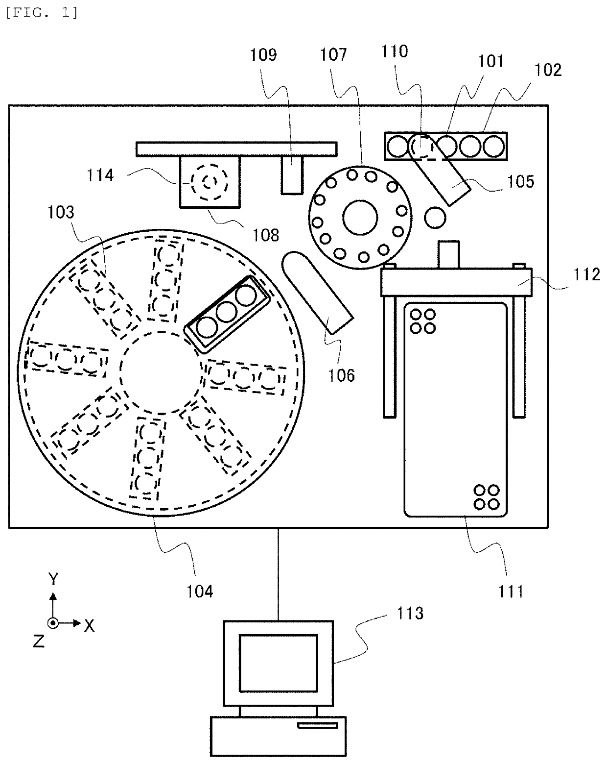
[0017]An example of the overall configuration of an automatic analyzer according to the present embodiment will be described with reference to FIG. 1. The automatic analyzer includes a sample transport unit 102, a reagent storage 104, a sample dispensing unit 105, a reagent dispensing unit 106, a reaction promotion part 107, a measurement unit 108, and a control unit 113. Each of the parts will be described below. The vertical direction is defined as Z direction, and the horizontal plane is defined as XY plane.
[0018]The sample transport unit 102 transports a sample container 101 accommodating a sample such as blood or urine to a sample aspiration position 110. The reagent storage 104 stores a reagent container 103 accommodating a reagent to be used for analysis in a predetermined temperature range.
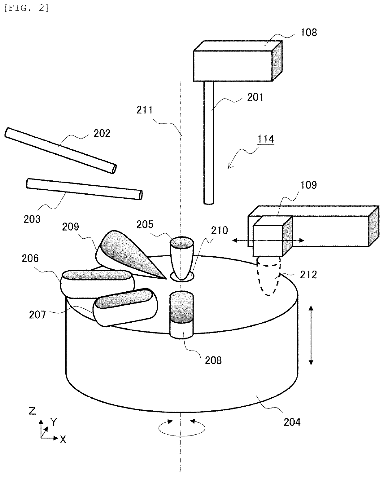
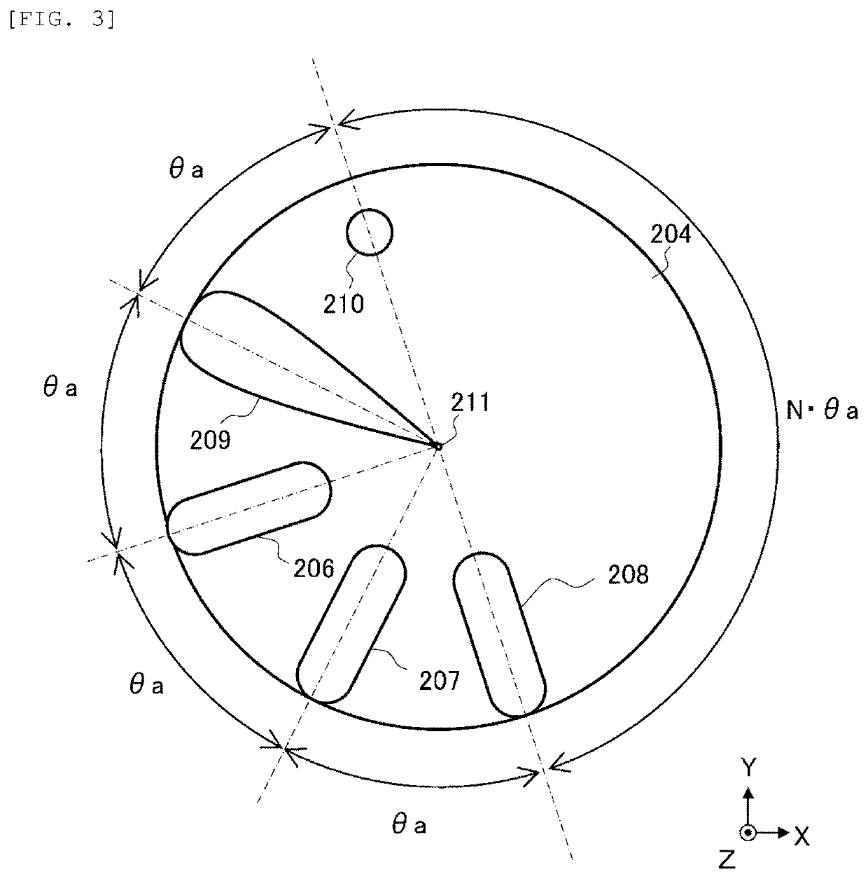
[0019]The sample dispensing unit 105 dispenses the sample from the sample containers 101 transported to the sample aspiration position 110 to a reaction vessel arranged in the reaction pro...
embodiment 2
[0029]Embodiment 1 describes that the control related to the rotation of the holding unit 204 is simplified by setting the angle between adjacent containers of the containers held by the holding unit 204 as an integer multiple of the predetermined angle θa. When the containers held by the holding unit 204 include a plurality of reagent containers accommodating reagents, and reagent nozzles supplying the reagents to each of the plurality of reagent containers, it is desirable that each reagent be supplied simultaneously from all reagent nozzles. Therefore, in the present embodiment, the reagent nozzles are arranged so that the control related to the rotation of the holding unit 204 can be simplified and a plurality of reagents can be supplied simultaneously.
[0030]An arrangement example of the reagent containers and the reagent nozzles held by the holding unit 204 in the present embodiment will be described with reference to FIG. 4. Similar to Embodiment 1, the holding unit 204 in the...
embodiment 3
[0033]Embodiment 1 describes that the control related to the rotation of the holding unit 204 is simplified by setting an angle between adjacent containers of containers held by the holding unit 204 as an integer multiple of the predetermined angle θa. Embodiment 2 describes that the angle between reagent nozzles is set so that a plurality of reagents can be supplied simultaneously. When a reagent nozzle whose position is fixed is provided in addition to the aspiration nozzle 201, it is not desirable for the nozzle to come into contact with a container that is not accessible. For example, in a case where the aspiration nozzle 201 comes into contact with the third reagent container 208 when the first reagent is supplied from the first reagent nozzle 202 to the first reagent container 206, the third reagent attached to the aspiration nozzle 201 adversely affects the measurement result of the measurement unit 108. Therefore, in the present embodiment, the nozzles are arranged so as to ...
PUM
 Abstract
Description
Claims
Application Information
 - R&D
- Intellectual Property
- Life Sciences
- Materials
- Tech Scout
- Unparalleled Data Quality
- Higher Quality Content
- 60% Fewer Hallucinations
Browse by: Latest US Patents, China's latest patents, Technical Efficacy Thesaurus, Application Domain, Technology Topic, Popular Technical Reports.
© 2025 PatSnap. All rights reserved.Legal|Privacy policy|Modern Slavery Act Transparency Statement|Sitemap|About US| Contact US: help@patsnap.com


