
Fuel cell system

Pending Publication Date: 2022-10-06
HONDA MOTOR CO LTD
View PDF0 Cites 0 Cited by
  • Summary
  • Abstract
  • Description
  • Claims
  • Application Information

AI Technical Summary

Benefits of technology

The present invention is aimed at providing a fuel cell system that can maintain one's power output even if the voltage level drops. This is achieved by increasing the generated current command value when the voltage level decreases, while keeping the power generation control constant. This simplifies the control system. Additionally, the invention also provides a method for controlling the fuel gas concentration in the anode of the fuel cell, without affecting the generated power. This helps in preventing a decrease in fuel gas concentration and maintaining the power output of the fuel cell.

Problems solved by technology

However, in the technique disclosed in JP 2019-114351 A, when the on-off valve of the connection flow path is opened, the voltage of the power generation cell decreases because of a shortage of the oxygen-containing gas that contributes to the power generation on the cathode side, due to the catalytic reaction.
Therefore, in a fuel cell system in which the generated current of the fuel cell is controlled based on a generated current command value, there is a problem that the generated power decreases.

Method used


Image

  • Fuel cell system
  • Fuel cell system
  • Fuel cell system

Examples


first embodiment

[Configuration]

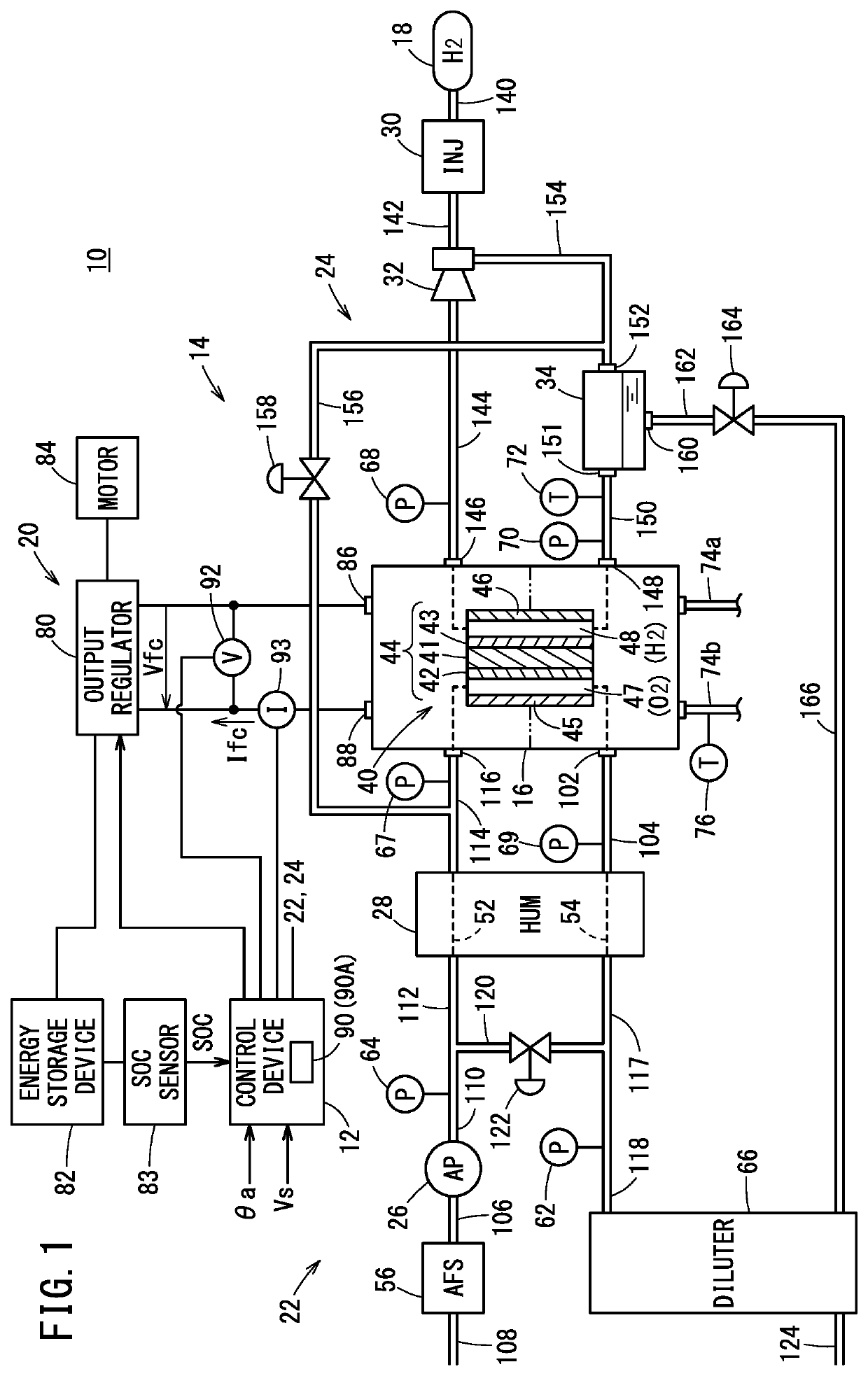
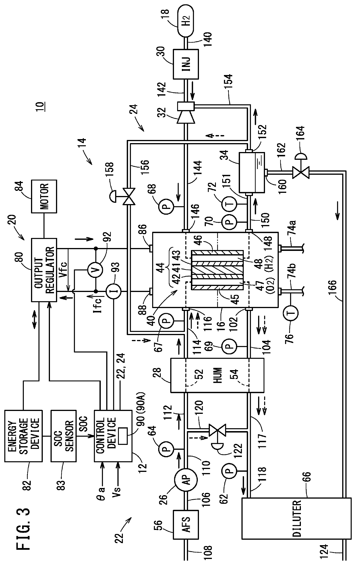
[0029]FIG. 1 is a schematic block diagram showing the configuration of a fuel cell vehicle 10 in which a fuel cell system 14 according to a first embodiment is incorporated.

[0030]The fuel cell vehicle 10 includes a control device 12 for controlling the entire fuel cell vehicle 10, the fuel cell system 14, and an output unit 20 electrically connected to the fuel cell system 14.

[0031]The fuel cell system 14 is basically constituted by a fuel cell stack (also referred to simply as a fuel cell) 16, a hydrogen tank 18, an oxygen-containing gas-related device 22, and a fuel gas-related device 24.

[0032]The oxygen-containing gas-related device 22 includes an air pump 26 and a humidifier (HUM) 28.

[0033]The fuel gas-related device 24 includes an injector (INJ) 30, an ejector (EJT) 32, and a gas-liquid separator 34.

[0034]In the fuel cell stack 16, a plurality of power generation cells 40 are stacked. The power generation cells 40 each include a membrane electrode assembly 44, an...


PUM


Abstract

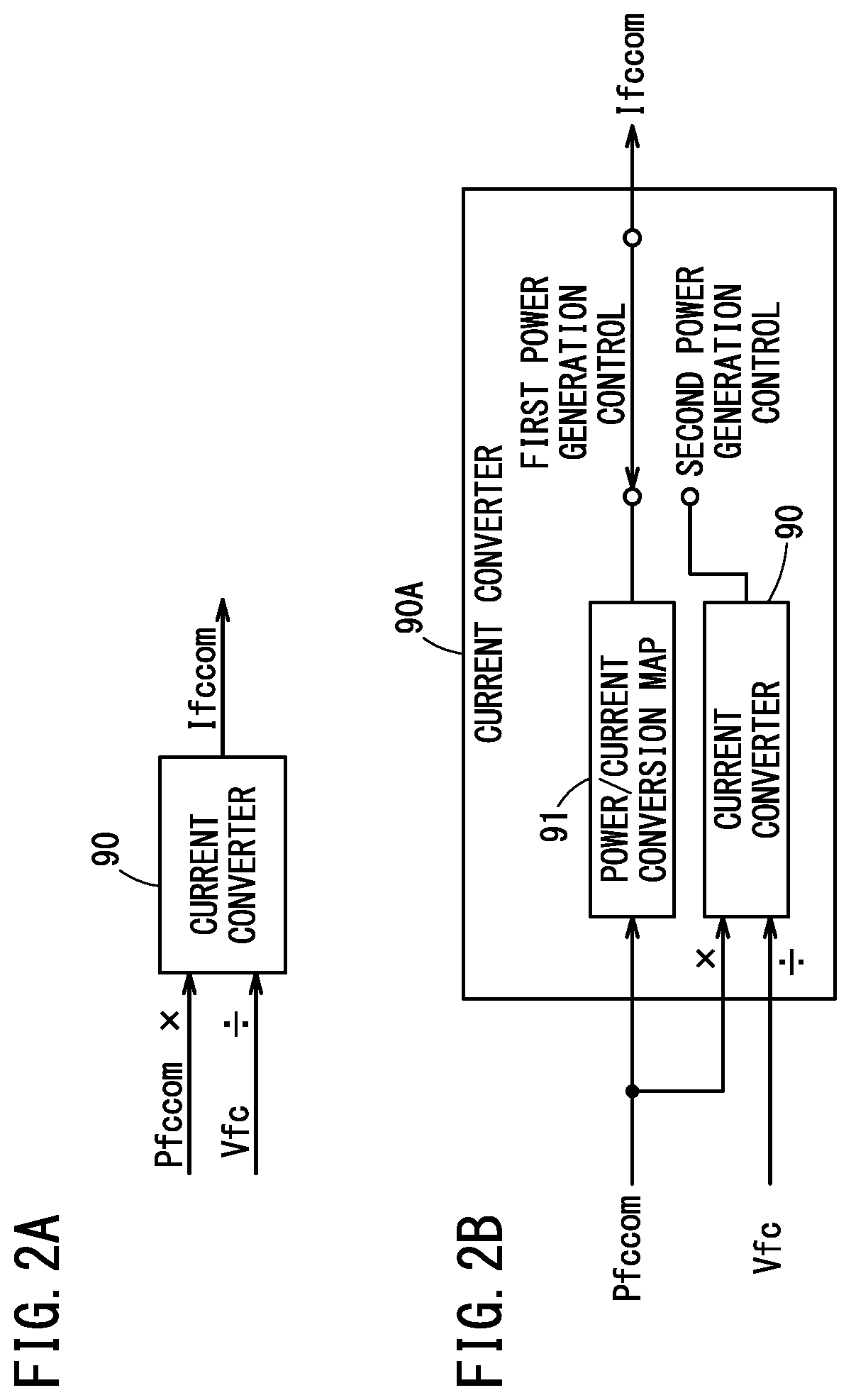
When controlling the power generation state of a fuel cell stack based on a generated current command value, a control device sets the generated current command value based on a generated power command value and a generated voltage acquired by a voltage sensor such that the following expression is satisfied, regardless of whether a bleed valve is opened or closed: generated current command value=generated power command value / generated voltage.

Description

CROSS-REFERENCE TO RELATED APPLICATIONS[0001]This application is based upon and claims the benefit of priority from Japanese Patent Application No. 2021-058974 filed on Mar. 31, 2021, the contents of which are incorporated herein by reference.BACKGROUND OF THE INVENTIONField of the Invention[0002]The present invention relates to a fuel cell system including a fuel cell that generates power by means of a fuel gas supplied to an anode through a fuel gas supply flow path, and an oxygen-containing gas supplied to a cathode through an oxygen-containing gas supply flow path.Description of the Related Art[0003]For example, a solid polymer electrolyte fuel cell is provided with a membrane electrode assembly (MEA) in which an anode is disposed on one surface of an electrolyte membrane made of a polymer ion exchange membrane and a cathode is disposed on the other surface of the electrolyte membrane. A power generation cell (unit cell) is formed by sandwiching the membrane electrode assembly b...

Claims


Application Information

Patent Timeline
IPC IPC(8): H01M8/04858H01M8/04537H01M8/04746B60L58/30
CPCH01M8/04932H01M8/04552H01M8/04753B60L58/30H01M2250/20H01M8/04089H01M8/04992Y02E60/50B60L58/33B60L1/02B60L3/0053
Inventor SAKAI, RYOJIINOUE, KAZUHIDENAKAGAWA, TAKUTO
Owner HONDA MOTOR CO LTD
Learn More