Embedded optical fingerprint recognition display device

一种指纹辨识、显示设备的技术,应用在指纹辨识领域,能够解决增加组装的困难度、增加加工程序、成本提高等问题,达到良率与成本降低、简化物料控管、增加防水性的效果

Active Publication Date: 2022-05-13
FOCALTECH ELECTRONICS LTD
View PDF11 Cites 0 Cited by
  • Summary
  • Abstract
  • Description
  • Claims
  • Application Information

AI Technical Summary

Problems solved by technology

However, when cutting the display screen 220 in a different shape, it is necessary to cut the related components of the display screen (such as substrate, light guide plate, thin film transistor layer, ..., protective glass, etc.), which increases many processing procedures and increases the difficulty of assembly. degree, which increases the cost significantly

Method used


Image

  • Embedded optical fingerprint recognition display device
  • Embedded optical fingerprint recognition display device
  • Embedded optical fingerprint recognition display device

Examples


Embodiment Construction

[0072] In order to make the objectives, technical solutions and advantages of the present invention clearer, the present invention will be further described in detail below with reference to the accompanying drawings and embodiments. It should be understood that the specific embodiments described herein are only used to explain the present invention, but not to limit the present invention.

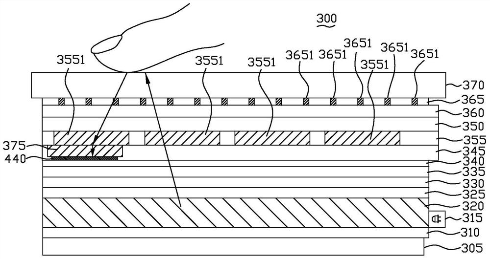
[0073] image 3 It is a schematic cross-sectional view of the embedded optical fingerprint identification display device 300 of the present invention. The in-cell optical fingerprint identification display device 300 includes a support layer (Bezel) 305, a reflector (Reflector) 310, at least one light source 315, a light guide plate (Light Guide Plate) 320, a diffuser plate (Diffuser) 325, A Rear Bright Enhancement Film (RBEF) 330, a Front Bright Enhancement Film (FBEF) 335, a lower polarizing layer 340, a thin film transistor layer 345, a display material layer 350, a touch sensor The e...


PUM


Abstract

The present invention proposes an embedded optical fingerprint recognition display device, which includes at least one light source, a light guide plate, a thin film transistor layer, and a touch sensing and sharing electrode layer. The light guide plate guides the light direction of at least one light source. The thin film transistor layer is located on one side of the light guide plate, which has several pixel circuits, several photosensitive circuits, several scanning lines and several data lines. The several scanning lines and several data lines are based on the first and second directions set up. The touch sensing and shared electrode layer is located on the side of the thin film transistor layer facing away from the light guide plate, and has several transparent sensing electrode blocks, and the several transparent sensing electrode blocks are arranged according to the first and second directions, wherein, The plurality of photosensitive circuits receive the reflected light of the at least one light source to generate an optical fingerprint image.

Description

technical field [0001] The present invention relates to the technical field of fingerprint identification, in particular to an embedded optical fingerprint identification display device. Background technique [0002] The competition in the mobile phone market is becoming increasingly fierce. Therefore, many functions have been added to the mobile phone design, such as touch detection, fingerprint recognition and other functions. At the same time, in order to reduce the thickness of the mobile phone and reduce the assembly process, the current mobile phone mainly uses in-cell touch detection technology. figure 1 It is a schematic diagram of an existing mobile phone 100 . As shown in the figure, it has a fingerprint identification module 110 and a touch screen 120 . Since the fingerprint identification module 110 is placed on the front of the mobile phone, the area that can be displayed by the touch screen 120 of the mobile phone is reduced. [0003] In the design of mobil...

Claims


Application Information

Patent Timeline
Patent Type & Authority Patents(China)
IPC IPC(8): G06V40/13
Inventor 萧培宏
Owner FOCALTECH ELECTRONICS LTD
Why Eureka
Try Eureka