
Head-mounted display and control apparatus and method

Active Publication Date: 2021-05-04
BAE SYSTEMS PLC
View PDF10 Cites 0 Cited by
  • Summary
  • Abstract
  • Description
  • Claims
  • Application Information

AI Technical Summary

Benefits of technology

The present invention is a head-mounted display that can display all the information a person needs without obscuring their view. It only requires one or a few control devices to interact with the data, making the control panel easier to use and providing a more intuitive display.

Problems solved by technology

However, as missions become more complex and the quantity of data required to be assimilated increases accordingly, a careful balance needs to be maintained.
Some of this data can be displayed within the operative's view of the real world, as described above, but putting displays in the operative's vision can be very dangerous, as it may obscure their view of a physical entity in the outside world or safety critical parameters in the head-up display (HUD) in the cockpit.
Furthermore, for interaction with each type of data, a different control device is typically required to be used, which results in a very complex control panel.

Method used


Image

  • Head-mounted display and control apparatus and method
  • Head-mounted display and control apparatus and method
  • Head-mounted display and control apparatus and method

Examples


Embodiment Construction

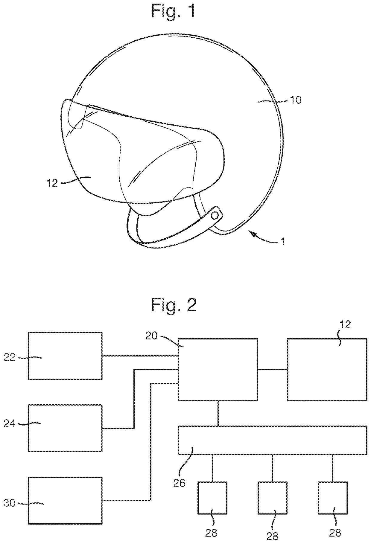
[0019]Referring to FIG. 1 of the drawings, a display apparatus according to an exemplary embodiment of the present invention comprises an integrated two-part helmet-mounted display (HMD) 1 comprising a protective helmet 10 configured, in use, to cover the crown, back and sides of a wearer's head, and a see-through (translucent or transparent) visor 12, and a stereoscopic colour display screen (not shown in FIG. 1). The visor 12 extends between the side portions of the protective helmet 10 and is configured, in use, to cover a wearer's eyes such that they can see through the visor and the screen is arranged and configured to project images displayed thereon into the wearer's view of the real-world environment through the visor (via transmitted / reflected light), such that they can also see any symbology or images displayed on the screen. In an exemplary embodiment of the present invention, the screen provides a fully overlapped, 40-degree, binocular display. This type of helmet-mounte...


PUM


Abstract

An apparatus and method for displaying an operational area, the apparatus comprising a headset (10) for placing over a user's eyes, the headset including a viewing device (12) configured to provide to said user, in use, a view of a real-world environment, a display generating device for depicting an operational area, said operational area being defined within said real-world environment and comprising a plurality of functional regions each defining a different one or more selectable functions or operations that can be performed in respect of said operational area, the apparatus being configured to transfer image data from said display generating device into said user's view of said real-world environment at said viewing device to generate an augmented reality environment, the apparatus further comprising a control module (26) including a control device (28) configured to be selectively communicably coupled to all of said functional regions to enable a user to selectively perform the respective one or more functions or operations associated therewith, wherein the control device (28) is communicably coupled to a selected functional region only in response to a respective actuation signal, and an eye tracker module (24) configured to monitor said user's gaze relative to said augmented reality environment, in use, and, when said user's gaze is directed at a selected functional region displayed therein, generate and transmit to said control module (26) a said actuation signal and when said user's gaze is no longer directed at said selected functional region, cause said control device (28) to be decoupled therefrom.

Description

RELATED APPLICATIONS[0001]This application is a national phase application filed under 35 USC § 371 of PCT Application No. PCT / GB2018 / 052560 with an International filing date of Sep. 10, 2018 which claims priority of GB Patent Application 1714572.3 filed Sep. 11, 2017 and EP Patent Application 17190442.8 filed Sep. 11, 2017. Each of these applications is herein incorporated by reference in its entirety for all purposes.FIELD OF THE INVENTION[0002]This invention relates generally to a head-mounted display apparatus and method and, more particularly, to a head-mounted display apparatus and method incorporating a control module for enabling a user to interact with regions of an operational area displayed on a head-mounted display screen.BACKGROUND OF THE INVENTION[0003]It is known, particularly in the field of military fighter aircraft and the like, to provide a helmet-mounted display (HMD), wherein a helmet having a transparent visor is provided with a display generating device, such ...

Claims


Application Information

Patent Timeline
IPC IPC(8): G02B27/00G02B27/01G06F3/01G06T19/00
CPCG02B27/0093G02B27/017G06F3/012G06F3/013G06T19/006G06F3/011G06F3/0482
Inventor JAMES, IAN GEOFFREYRIDGE, EDMOND RICHARDSIMM, DAVID JOHNPIGOTT, MALCOLM GRANT
Owner BAE SYSTEMS PLC
Learn More