
Communication control system

Inactive Publication Date: 2005-09-20
PANASONIC CORP
View PDF12 Cites 0 Cited by
  • Summary
  • Abstract
  • Description
  • Claims
  • Application Information

AI Technical Summary

Benefits of technology

[0011]The object of the present invention is to simplify cell discard control to discard cells from a cell buffer assembly and enhance the efficiency of the cell discard control in multiplex communication in the form of fixed-length cells.
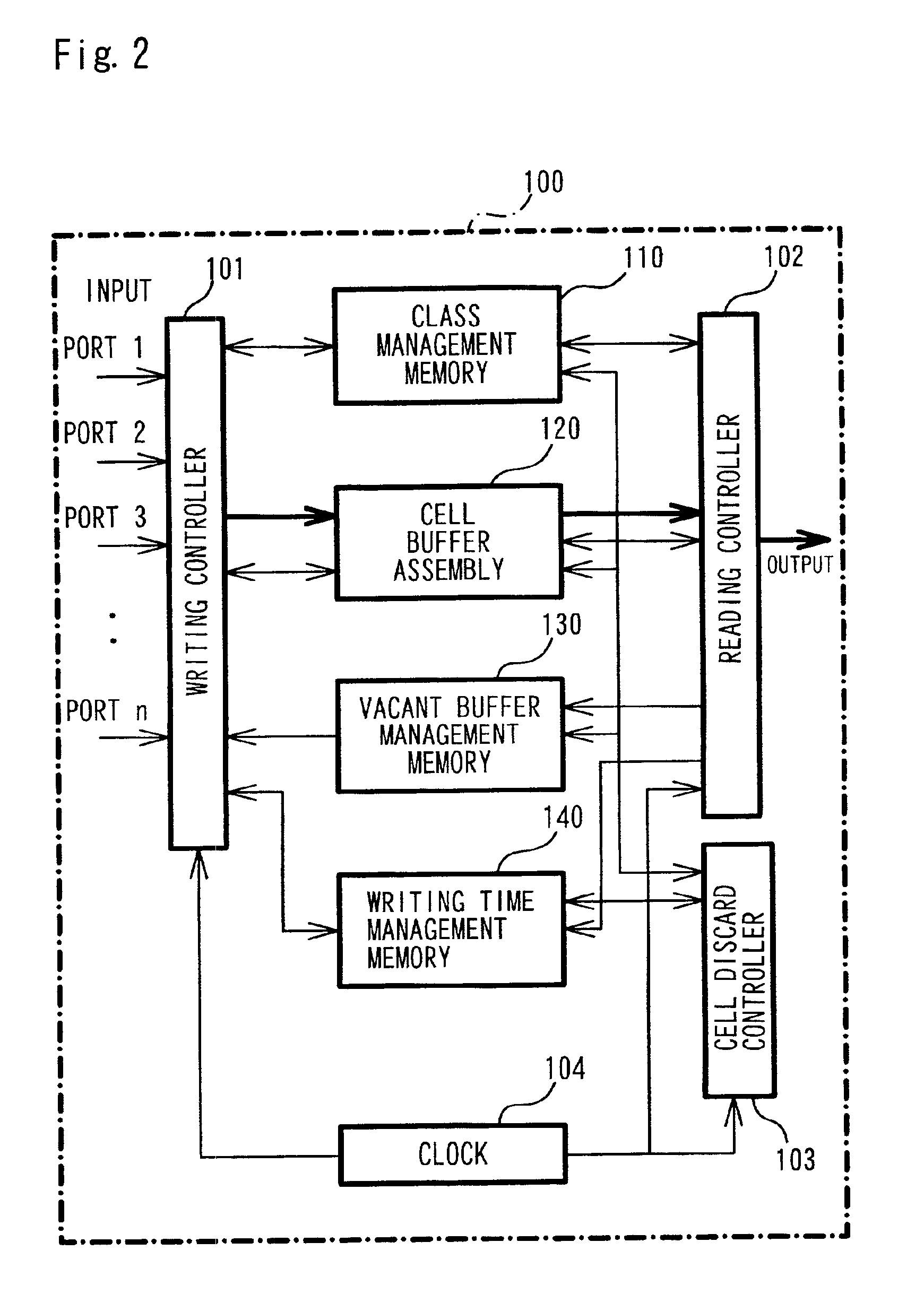
[0013]In the communication control system of the present invention, the cell discard controller is provided to carry out the cell discard control, independently of the cell writing control and the cell reading control. This arrangement simplifies the control procedure in the buffer management unit, while ensuring flexible adjustment of the execution timing of the cell discard control.
[0015]The elapsed time period may be an elapsed time since storage of the cell, the number of steps in the control process after storage of the cell, or the number of cycles of the cell discard control process. The cell discard operation based on the elapsed time may be actualized by the structure using a writing time management unit that maps each cell to a writing time of the cell and manages the mapping. Such application based on the elapsed time readily ensures the desired MCR.
[0016]In the structure that discards the cell based on the elapsed time, it is preferable that the writing time management unit includes a writing time buffer and a related information storage unit. The writing time buffer stores a writing time of each cell in time series. The related information storage unit stores related information, which relates data stored in the cell buffer assembly to data stored in the writing time buffer. Simple retrieval of the writing time buffer readily identifies the cell having a long elapsed time. This arrangement enhances the efficiency of the cell discard control.
[0017]The related information storage unit may be provided as a separate memory area from the cell buffer assembly and the writing time buffer. In this case, it is required to map the storage area in the cell buffer assembly to the storage area in the writing time buffer. The related information storage unit may be provided inside the cell buffer assembly or the writing time buffer. In the former case, for example, the storage area in the writing time buffer may be mapped to each cell stored in the cell buffer assembly. This reduces the required storage capacity of the related information storage unit.
[0020]When the buffer management unit has the above structure, it is preferable that the cell discard controller deletes information on a place of storage of the cell to be discarded from the cell management unit, and transmits the place of storage as a new vacant area to the vacant buffer management unit, thereby implementing discard of the cell. In this application, simple update of the management information attains discard of cells without reading a discard cell from the cell buffer assembly. This arrangement desirably speeds up the cell discard control.

Problems solved by technology

This prior art communication control technique does not require an individual cell buffer for each input port, thus desirably reducing the total capacity of the cell buffer.
The prior art system requires relatively complicated control procedures, since the reading controller performs the two different control processes, that is, the cell reading control and the cell discard control.
This lengthens the total processing time.
This lowers the efficiency of processing.

Method used


Image

  • Communication control system
  • Communication control system
  • Communication control system

Examples


Embodiment Construction

[0041]A mode of carrying out the present invention is discussed below as one embodiment in the following sequence:[0042]A. Configuration of System[0043]B. Communication Control Process[0044]B1. Writing Control Process[0045]B2. Reading Control Process[0046]B3. Cell Discard Control Process[0047]B4. Modification of Cell Discard Control Process

[0048]A. Configuration of System

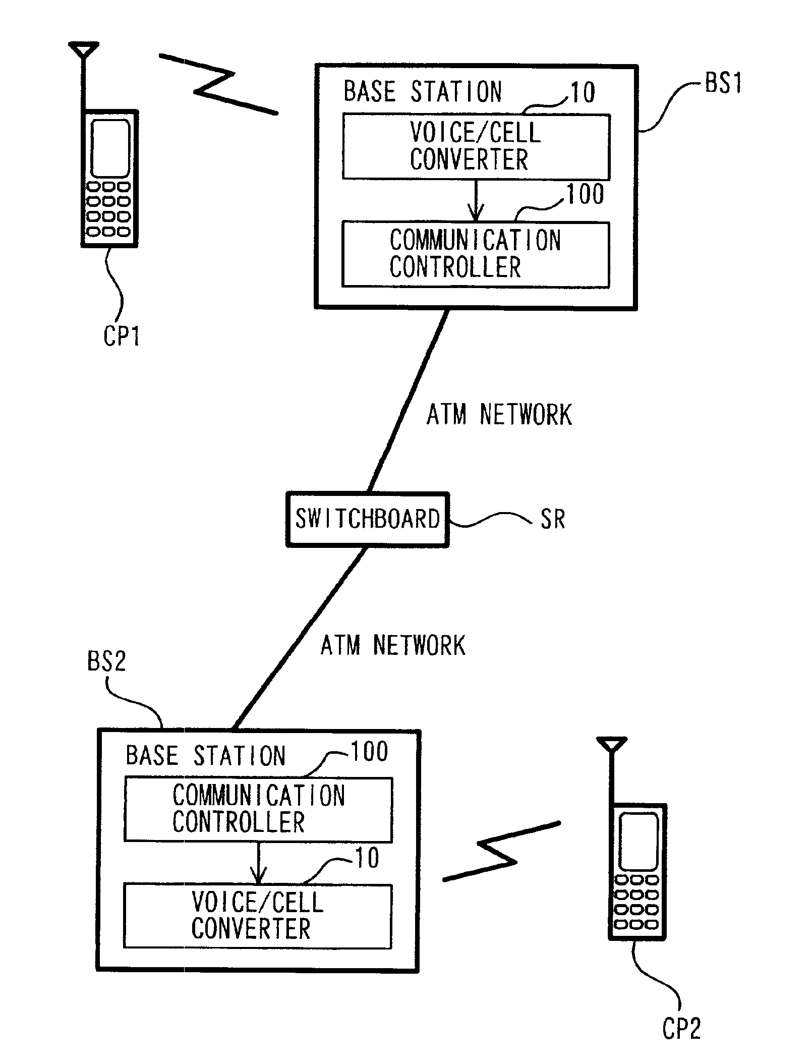
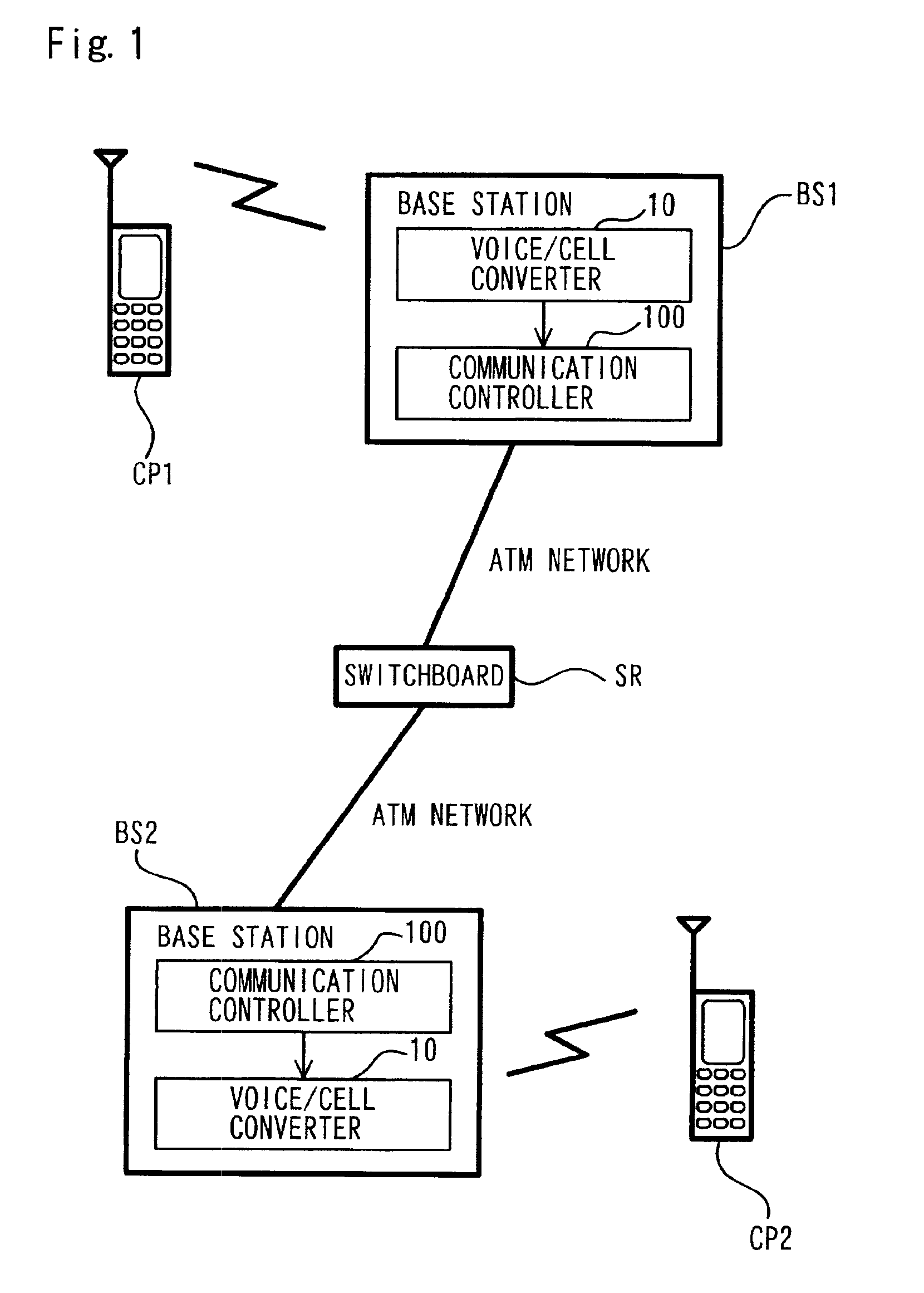
[0049]FIG. 1 schematically illustrates the configuration of a communication system in one embodiment of the present invention. The illustration regards the configuration in the case of voice communication between cellular phones CP1 and CP2. Audio signals input into the cellular phone CP1 are transmitted to a base station BS1 by wireless. The base station BS1 is capable of simultaneously communicating with a plurality of cellular phones. Each cellular phone is mapped to each input port on the base station BS1 for communication.

[0050]The base station BS1 has a voice / cell converter 10 and a communication controller 10...


PUM


Abstract

The communication control system of the present invention includes a cell buffer assembly that is common to a plurality of input ports and stores cells. A writing controller and a reading controller respectively control a process of writing a cell into the cell buffer assembly and a process of reading a cell from the cell buffer assembly. A writing time management memory maps a writing time of each cell to each area in the cell buffer assembly and manages the mapping. A cell discard controller discards a cell having a long elapsed time since the writing time stored in the writing time management memory by the processing, which is independent of the processing by the writing controller and the reading controller. The arrangement of discarding the oldest cell independently of the writing and reading operations enables efficient discard of cells, while ensuring a desired communication rate. This arrangement simplifies the cell discard control and enhances its efficiency in the case of convergence in multiplex communication in the form of fixed-length cells.

Description

BACKGROUND OF THE INVENTION[0001]1. Field of the Invention[0002]The present invention relates to a communication control technique that controls multiplex communication in the form of fixed-length cells. More specifically the present invention pertains to a buffer management technique to manage cells stored in a cell buffer assembly.[0003]2. Description of the Related Art[0004]A known technique of high-speed transfer of large-capacity data, such as movie data, is asynchronous transfer mode (ATM). ATM time division data, for example, voice data, static image data, or movie data, into fixed-length, 53-byte cells and carries out communication in the form of such cells. Transmission of the time-divided cells enables signals from a plurality of input ports to be multiplexed. The cells are temporarily stored in a buffer included in a communication controller or a multiplexer, and are read from the buffer at a desired rate or at desired time intervals set for each communication.[0005]There...

Claims


Application Information

Patent Timeline
IPC IPC(8): H04L12/56H04Q11/04H04B7/26H04L13/08H04L47/32H04W28/14H04W88/08H04W88/14
CPCH04L49/254H04L49/30H04Q11/0478H04L49/205H04L2012/5607H04L2012/5647H04L2012/5651H04L2012/5652H04L2012/5672H04L2012/5679H04L2012/5681
Inventor MIURA, KAZUEYAGUCHI, HIROKI
Owner PANASONIC CORP
Learn More