Flexible printed circuit board

a printed circuit board and flexible technology, applied in the direction of printed circuit assembling, printed circuit manufacturing, printed circuit aspects, etc., can solve the problem that air in the through holes cannot escape, and achieve the effect of sufficient strength and satisfactory conductivity for a long tim

Inactive Publication Date: 2017-12-07
MINEBEA CO LTD
View PDF26 Cites 4 Cited by
  • Summary
  • Abstract
  • Description
  • Claims
  • Application Information

AI Technical Summary

Benefits of technology

[0006]An object of the present teaching is to provide a flexible printed circuit board having an electrode, which is connected or joined to a counterpart electrode via a solder joint with sufficient strength so as to provide satisfactory conductivity for a long time.

Problems solved by technology

Specifically, when pre-solder (pre-tin) is melted so that the through holes are filled with the pre-solder, the air in the through holes is not allowed to escape.

Method used


Image

  • Flexible printed circuit board
  • Flexible printed circuit board
  • Flexible printed circuit board

Examples


Embodiment Construction

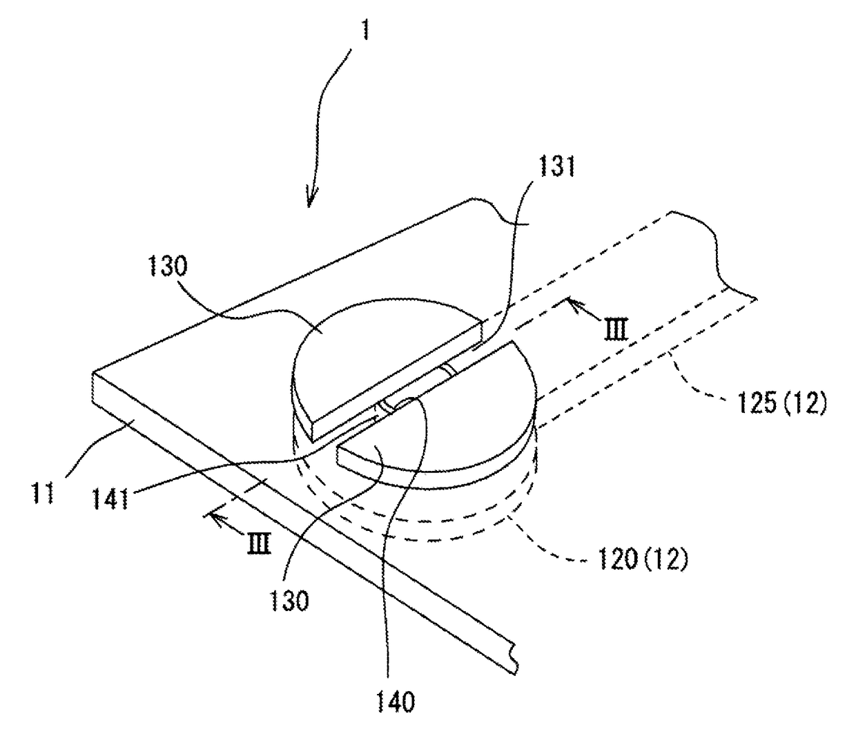
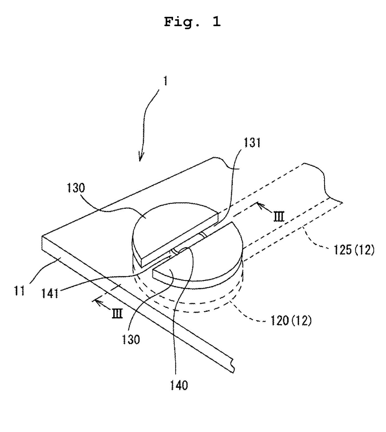
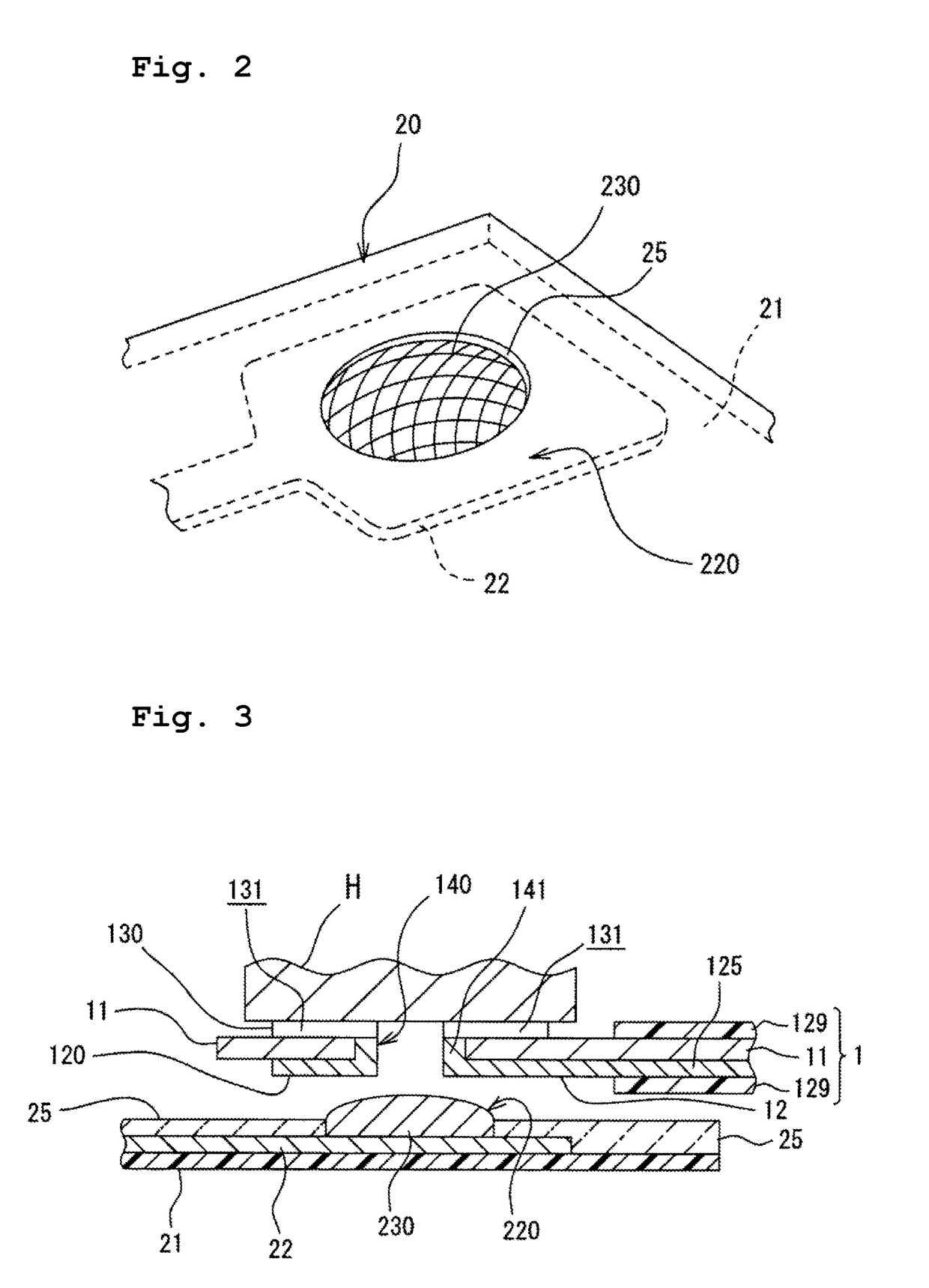
[0017]In the following, an explanation will be made with reference to the drawings about a flexible printed circuit board 1 related to an embodiment of the present teaching. FIG. 1 is a perspective view of the flexible printed circuit board 1 related to the embodiment of the present teaching as viewed from the side of one of lands (heating side land 130) of an electrode provided in the flexible printed circuit board 1. FIG. 2 is a perspective view depicting a counterpart electrode to be connected to the flexible printed circuit board 1 depicted in FIG. 1 with soldering. FIGS. 3 and 4 are illustrative views chronologically illustrating states that the flexible printed circuit board 1 related to this embodiment is crimped or pressure welded to a part of another flexible printed circuit board having the counterpart electrode through thermocompression bonding.

[0018]In the drawings, the sizes, thicknesses, and dimensions of components or parts related to the embodiment and modified embod...


PUM


Abstract

There is provided a flexible printed circuit board. The flexible printed circuit board includes: a flexible insulation layer having a first surface and a second surface; a first land which is conductive and which is provided on the first surface of the flexible insulation layer; and a conductive member which is provided on the second surface of the flexible insulation layer. A recess is formed on the first land.

Description

CROSS REFERENCE TO RELATED APPLICATION[0001]This is a Division of application Ser. No. 14 / 815,413 filed Jul. 31, 2015, which claims priority from Japanese Patent Application No. 2014-159097 filed on Aug. 4, 2014, and titled “ FLEXIBLE PRINTED CIRCUIT BOARD”, the disclosure of which is incorporated herein by reference in its entirety.BACKGROUND OF THE INVENTIONField of the Invention[0002]The present teaching relates to a flexible printed circuit board which can be electrically connected to a counterpart electrode reliably.Description of the Related Art[0003]For example, a strain gage measuring the strain or distortion of a structure is formed in one flexible printed circuit board (a first flexible printed circuit board) which is very thin. In order to extract or take out the output from the strain gage, another flexible printed circuit board (a second flexible printed circuit board) for transmitting a signal is joined to the first flexible printed circuit board with soldering so that...

Claims


Application Information

Patent Timeline
Patent Type & Authority Applications(United States)
IPC IPC(8): H05K1/11H05K1/03H05K3/36
CPCH05K1/118H05K1/116H05K3/363H05K1/0393H05K1/113H05K1/147H05K2201/09036H05K2201/0969H05K2201/09745H05K2203/1178
Inventor INAMORI, DOHAKUKASHINO, TAKASHI
Owner MINEBEA CO LTD
Why Eureka
Try Eureka